NOTE: FOR UK ONLY
As the colors of the wires in the mains lead of this apparatus may not correspond with the
colored markings identifying the terminals in your plug, proceed as follows: (1) The wire which
is colored green and yellow must be connected to the terminal which is marked by the letter E, or by
the earth symbol, or colored green or green and yellow. (2) The wire which is colored blue must be
connected to the terminal which is marked with the letter N, or the color black. (3) The wire which is
colored brown must be connected to the terminal which is marked with the letter L or the color red.
(2) POWER SWITCH
Used to turn AC mains power on or off. Place the switch in the (I) position to turn the unit on.
Return it to the (O) position to turn the unit off. The Status/Power LED (22 ) on the front of the
unit will illuminate to indicate the unit is on.
(3) FUSE
The fuse is located within the cap of the fuseholder. If the fuse should fail, IT MUST BE
REPLACED WITH THE SAME TYPE AND VALUE IN ORDER TO AVOID DAMAGE TO THE
EQUIPMENT AND TO PREVENT VOIDING THE WARRANTY. If the unit repeatedly blows
fuses, it should be taken to a qualified service center for repair.
WARNING: THE FUSE SHOULD ONLY BE REPLACED WHEN THE POWER CORD HAS
BEEN DISCONNECTED FROM ITS POWER SOURCE.
CAUTION: USING A FUSE LARGER THAN THE RECOMMENDED SIZE COULD RESULT
IN PERMANENT DAMAGE TO THE AMPLIFIER.
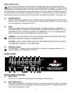
(4) SPEAKER JACKS
Two paralleled 1/4" speaker jacks are provided for connection to speaker enclosures. The
minimum speaker load impedance is 4 ohms.
FRONT PANEL:
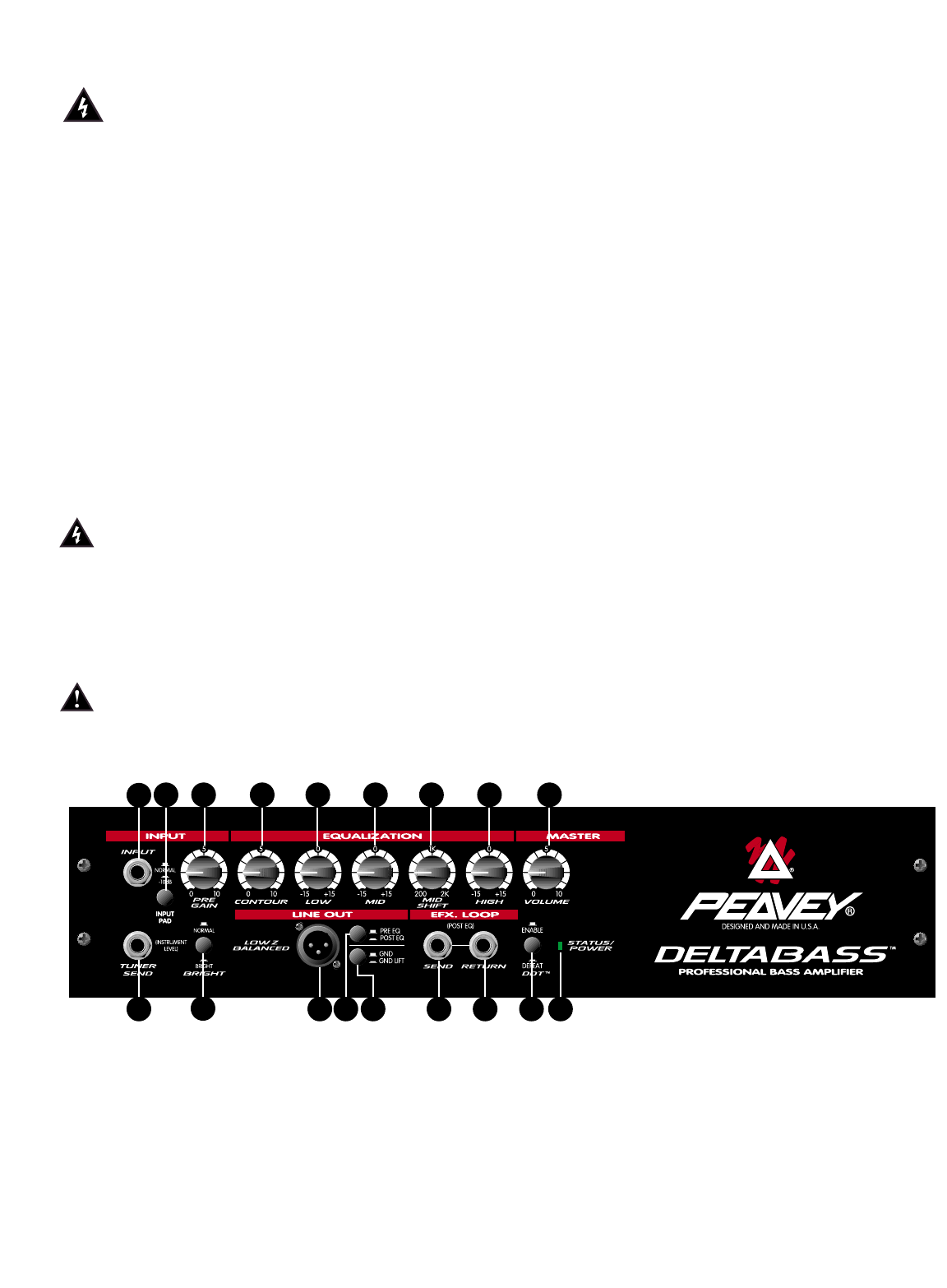
FRONT PANEL FEATURES
(5) INPUT JACK
This mono 1/4" input will accept signals from all types of bass pickups.
(6) INPUT PAD SWITCH
This switch is provided for instruments that have an extremely high output, which can result in
overdriving (distorting) the input stage. Depressing the switch to its “in” position reduces the
level of the input signal by 10 dB.
7
5
6 9 10 11 12 13 14 15
8
16 17 18 19 20 21 22
4


