


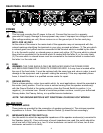
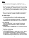
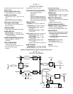
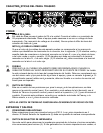
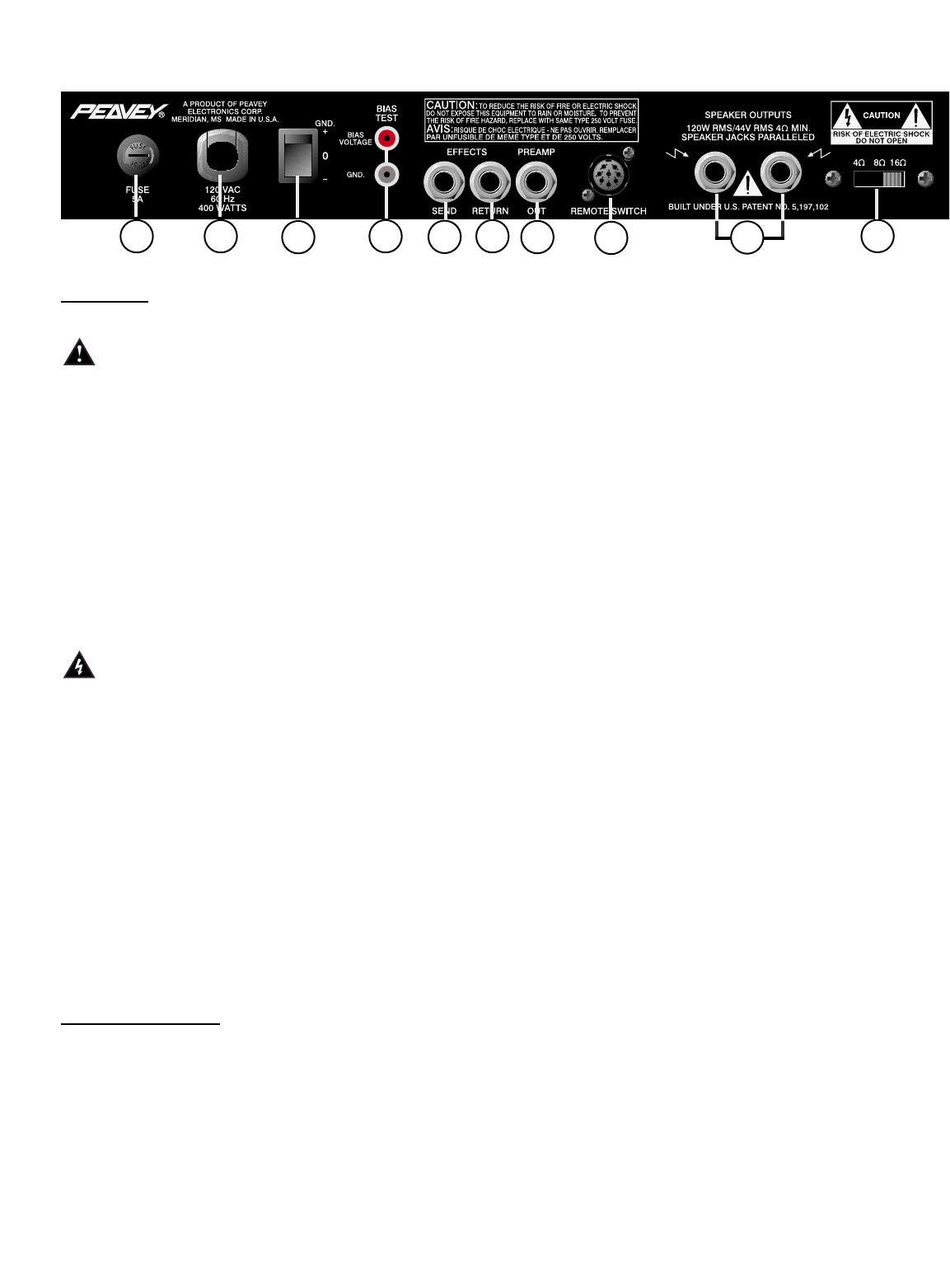
REAR PANEL FEATURES
P
OWER
(1) LINE CORD:
This line cord provides the AC power to the unit. Connect the line cord to a properly
grounded AC supply. Damage to the equipment may occur if improper line voltage is used.
(See voltage marking on unit.) Never remove or cut the ground pin of the line cord plug.
NOTE: FOR UK ONLY
As the colors of the wires in the mains lead of this apparatus may not correspond with the
colored markings identifying the terminals in your plug, proceed as follows: (1) The wire which
is colored green and yellow must be connected to the terminal which is marked by the letter
E, or by the earth symbol, or colored green or green and yellow. (2) The wire which is colored
blue must be connected to the terminal which is marked with the letter N, or the color black.
(3) The wire which is colored brown must be connected to the terminal which is marked with
the letter L or the color red.
(2) FUSE
WARNING: THE FUSE SHOULD ONLY BE REPLACED WHEN THE POWER CORD
HAS BEEN DISCONNECTED FROM ITS POWER SOURCE. A 5 amp fuse is located within
the cap of the fuse holder. It must be replaced with the same type and value in order to avoid
damage to the equipment and to prevent voiding the warranty. If the amp repeatedly blows
fuses, it should be taken to a qualified service center for repair.
(3) GROUND SWITCH
This is a three-position, rocker type switch which, for most applications, should be operated in
the center (zero) position. If hum or noise is noticed coming from the speaker enclosure(s)
with the Ground Switch in the center position, place the Ground Switch to positive (+) or
negative (-) to minimize hum. Should a hum/noise problem continue, consult your authorized
Peavey dealer, the Peavey factory, or a qualified service technician.
NOTE: THE GROUND SWITCH IS NOT FUNCTIONAL ON 220/240 VOLT MODELS.
INs
AND OUTs
(4) SPEAKER JACKS
These jacks are provided for the connection of speaker enclosure(s). The minimum speaker
impedance is 4 ohms. The Impedance Selector Switch (5) should be set accordingly.
(5) IMPEDANCE SELECTOR SWITCH (5)
Use this switch to select the appropriate impedance of the speaker enclosure(s) connected to
the Speaker Jacks (4). If two enclosures of equal impedance are used, the switch should be
set at one half of that value (e.g., two 16 ohm enclosures: set switch to 8 ohms; two 8 ohm
enclosures: set switch to 4 ohms).
2 1
3
10
7
8
9
6
5
4
4