


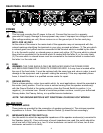
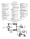
(6) REMOTE FOOTSWITCH JACK
This jack is provided for the connection of the supplied remote footswitch. The footswitch
cable should be plugged in before the amp is powered up. When the footswitch is plugged
into the Remote Footswitch Jack, the Channel Select switch (14) must be pressed to the “in”
position for remote selection of the Lead or Rhythm channel (right footswitch button). The On
and Off operation of Effects (left footswitch button) will work at all times. Remote selection of
Crunch gain boost (center footswitch button) is available only when the Crunch Switch (22) is
selected. See page 9 for detailed Footswitch diagram.
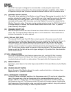
(7/8) EFFECTS SEND/EFFECTS RETURN
Signals are supplied to outboard effects or signal processing units by patching from the
Effects Send (7) output into the outboard unit(s) and back into the Effects Return (8) input
using shielded cables with 1/4" mono phone plugs. Only non-gain effects devices (chorus,
reverb, delay, etc.) should be used in the effects loop. If footswitch is used, “Effects” must be
selected (LED illuminated) for effects to work.
(9) PREAMP OUT
This output can be used to send a preamp signal from the 5150 II to a mixing console, tape
recorder, etc., using a shielded instrument cable. Patching from the PREAMP OUT does not
affect the normal operation of the amplifier.
BIAS
ADJUST SYSTEM
(10) BIAS TEST TERMINALS
These terminals, along with the adjustment knob behind the grill are provided to measure
and adjust the power amp tubes’ bias. The bias adjustment should only be done by a
qualified technician.
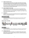
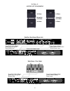
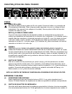
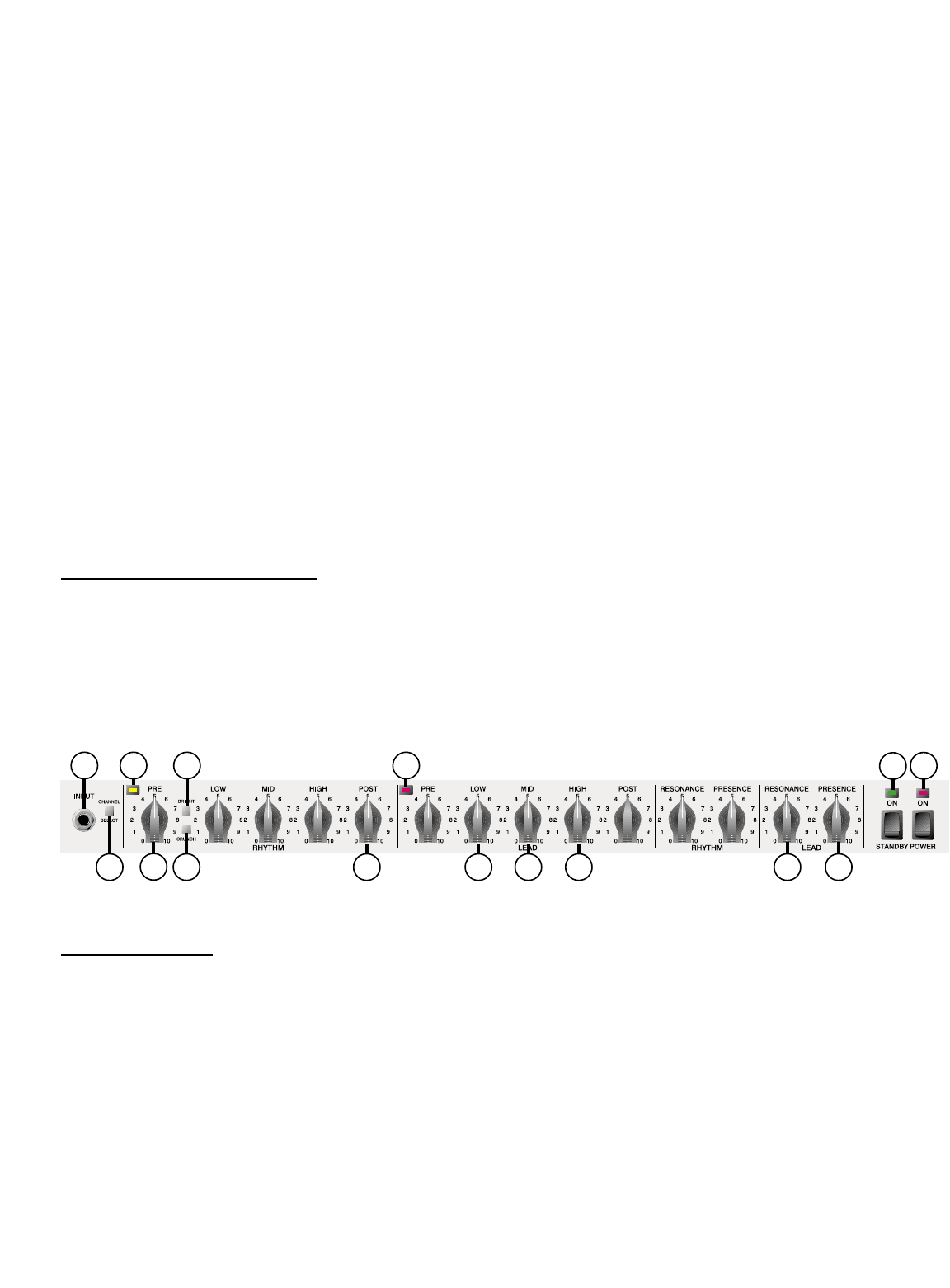
FRONT PANEL FEATURES
ON ST
ANDBY
(11) POWER SWITCH/LED
This switch supplies power to the unit. Depressed to the “ON” position, the red Power LED
indicator will illuminate above the Power Switch when power is being supplied to the unit.
(12) STANDBY SWITCH/LED
This switch allows the 5150 II to be placed in a non-operational standby mode. When the
Standby Switch is activated, the tubes remain hot and ready for instantaneous operation,
eliminating warm-up time. The Standby LED indicator above the switch will illuminate when
the amp is in the operational mode.
16
22 20 17 18 19 23 2414
5
12
11
1513 2115