


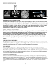

BACK PANEL FEATURES
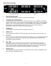
8. INPUT SECTION
The ICA
™
Series comes standard with plugable input connectors and individual channel rotary
attenuators. Connections at the input connector permit the audio signal ground to be
connected or lifted from the chassis ground.
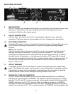
9. OUTPUT BARRIER STRIP
A barrier strip is provided for connection of loudspeakers with bare wire or spade lug
connectors. This barrier strip can accommodate up to two 10-gauge wires per terminal.
10. IEC POWER CONNECTOR
A standard IEC power connector is located at the upper left corner of the amplifier rear panel.
An AC mains cord having an appropriate AC plug for the intended operating voltage is
included.
NOTE: FOR UK ONLY
If the colors of the wires in the mains lead of this unit do not correspond with the colored
markings identifying the terminals in your plug, proceed as follows: (1) The wire that is
colored green and yellow must be connected to the terminal that is marked by the letter E,
the earth symbol, colored green, or colored green and yellow. (2) The wire that is colored
blue must be connected to the terminal that is marked with the letter N or the color black. (3).
The wire that is colored brown must be connected to the terminal that is marked with the
letter L or the color red.
11. CIRCUIT BREAKER
A resettable, protective AC circuit breaker is located at the upper left of the amplifier back
panel. If the breaker has tripped, push it back in to return the amplifier to operating condition.
If the breaker continues to trip, the amplifier needs servicing. Do not continue to reset the
breaker because severe internal damage and safety hazards could occur!
12. SEQUENTIAL TURN-ON CONNECTOR
The ICA
™
Series comes standard with remote-controllable sequential turn on enabled by
setting the front power switch to STANDBY. The amplifier is activated by applying a voltage
between 12 to 24 volts DC to the rear-mounted, 4-pin plugable terminal, and connecting the
ENABLE terminal to the 24 V DC+ terminal. When no voltage is present or the ENABLE
connection is opened, the amplifier will switch off. Other ICA Series amplifiers can be “daisy
chained” by connecting all 24 V DC+ terminals together, all COMMON terminals together, and
6
1110
9
12
13 8