


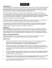

BRIDGED MODE DIAGRAM
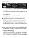
SPEAKER OUTPUT CONNECTIONS
Speakers are connected using the output barrier strip connectors. Spade lugs, ring tongues or bare
wire may be connected to the output barrier strip elements. The barrier strip can accommodate up to
two 10-guage wires per terminal. Make sure the amplifier is turned off before you change any output
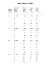
connections or jumpers. Consult the Wire Gauge Chart at the back of this manual to find a suitable
wire gauge to minimize losses of power in the speaker cables. Also, make sure that the load
impedance is not lower than that rated for the amplifier.
SIGNAL GROUND CONNECTION
Connections at the input connector permit the audio signal ground to be connected or lifted from the
chassis ground. When possible, the shield of the signal source connecting cable should connect to
the chassis ground. In some cases, however, particularly if an amplifier is being installed in an
existing system, this may result in a ground loop. If this happens, connect the shield to the signal
ground only. The chassis ground also connects to the AC ground internally. If the cable shield is
connected to the signal ground only, it will be clamped to +/- 0.6 V above or below chassis/AC
ground.
PROTECTION FEATURES
The ICA
™
Series incorporates protection features derived from Peavey’s extensive experience with
reliability. The amplifiers are ruggedly built from high-quality components and feature comprehensive
protection circuits to protect your amplifier from those “real world” occurrences.
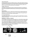
CLIP LIMITING
At the amplifier’s full power, or clipping point, the channel gain will automatically be reduced,
guarding the loudspeakers against damaging high power and continuous square waves that would
otherwise be produced. This is indicated by illumination of the CLIP LED. Normal program transients
will not trigger Clip Limiting, only steady or excessive clipping will. Operation is virtually transparent
in use and full signal bandwidth is maintained.
LOAD FAULT CORRECTION
™
LFC is an innovative circuit that will instantaneously reduce channel gain to allow the amplifier to
operate at a safe level into an abnormal load. LFC activation is indicated by illumination of the LFC
LED. Moderate activation of LFC is inaudible in normal use. In addition, if extreme low impedance or
a short circuit is encountered during high signal level conditions, the amplifier’s output relay will
open.
9
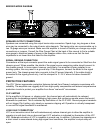
LEVEL B
-1
0
-6
-3
-10
-15
-30
-80
LEVEL A
-1
0
-6
-3
-10
-15
-30
-80
INPUT B
INPUT A
TM
A DIVISION OF PEAVEY ELECTRONICS CORP. MERIDIAN, MS MADE IN U.S.A.
MOUNT IN RACK ONLY
INSTALLER SUR SUPPORT DE MONTAGE SEULEMENT
24V DC+
ENABLE IN
COMMON
ENABLE OUT
OUTPUT POWER @ 4 OHMS IS 300 WATTS/CH
120 VAC
60 Hz
700 WATTS
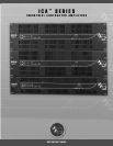
RCHITECTURAL
COUSTICS
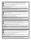
WARNING:
CAUTION
RISQUE DE CHOC ELECTRIQUE-NE PAS OUVRIR.
AVIS:
TO RAIN OR MOISTURE.
ELECTRIC SHOCK DO NOT EXPOSE THIS EQUIPMENT
TO REDUCE THE RISK OF FIRE OR
CLASS 2 WIRING
OUTPUT B OUTPUT A
(dB) (dB)
INDUSTRIAL CONTRACTOR AMPLIFIER
by
TM
600