


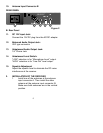
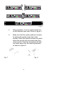

10. Antenna Input Connector B
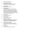
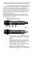
REAR PANEL
B. Rear Panel
11. DC 12V Input Jack:
Connect the 12V DC plug from the AC/DC adapter.
12. Balanced Audio Output Jack:
XLR type connector
13. Unbalanced Audio Output Jack:
1/4" Phone Jack
14. Unbalanced Level Switch:
“LOW” selection is for “Microphone-Level” output.
“HIGH” selection is for “Line-Out” level output.
15. Squelch Adjustment:
Adjust the squelch level to eliminate the RF noise
interference at the receiver.
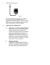
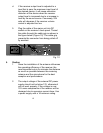
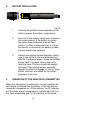
2. INSTALLATION OF THE RECEIVER
1. Install one of the antennas at the antenna
input connector A. Then install the other
antenna at the antenna input connector B.
Make sure both antennas are in the vertical
position.
Figure 2
5
11
12 13 14 15