


8
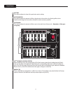
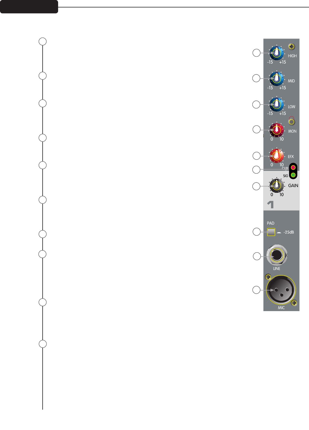
HIGH EQ
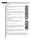
This High EQ shelving type of active tone control varies the treble frequency (±15 dB
at 12 kHz) and is designed to remove noise or add brilliance to the signal, depend-
ing on the quality of the source.
MID EQ
Mid EQ is a band pass (peak/notch) type of active tone control that varies the mid-
range frequencies (±15 dB at 450 Hz).
LOW EQ
A shelving type of active tone control that varies the bass frequency levels (±15 dB
at 70 Hz). Low EQ adds depth to thin-sounding signals or cleans up muddy ones. As
with any EQ‚ use sparingly. Too much of this EQ can give you a booming bottom end.
MON (monitor)
This control varies the level of each channel signal (pre-EQ) that is added
to the monitor mix.
EFX
The EFX control varies the level into the digital effects processor bus‚ adjusting
signal level from the individual channel to the digital processor. It is post gain and
will be affected by the gain control.
SIGNAL/CLIPPING INDICATOR
These LEDs illuminate green when a signal is present and red when clipping
occurs. If clipping occurs‚ turn the gain (7) down. If the channel clips when turning
the Level control up only slightly‚ try engaging the Pad switch (8).
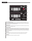
GAIN
This control sets the signal level sent to the main mix.
PAD
Pad attenuates the input signal by -25 dB. If you notice distortion from a particular
channel or if the channel becomes loud very quickly‚ try engaging this switch. In ad-
dition to increasing the dynamic range‚ the channel input can now accommodate a
higher input level before clipping occurs, which may be helpful when close-mic’ing
a loud guitar amp or drum kit, for example.
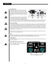
LINE INPUT
These line inputs are 1/4” balanced TRS inputs. The tip is the positive input which
may also be used for unbalanced inputs. A pad switch is provided to attenuate strong
signals present at this input. Note: The Mic input and the Line input cannot be used
simultaneously within the same channel.
MIC INPUT
These mic inputs are XLR balanced‚ low-impedance channel inputs optimized for a microphone or other
low-impedance source. Pin 2 is the positive input. Due to the wide range of gain adjustment‚ signal
levels as high as +10 dBV (2.45 V RMS) can be accommodated with the pad switch engaged. When the
phantom power is enabled‚ this connector has +48 V on pins 2 and 3 with pin 1 as the ground reference.
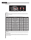
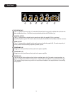
Front Panel
1
2
3
4
5
6
7
8
9
10
1
2
3
4
5
6
7
10
8
9
CHANNEL CONTROLS