


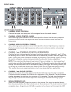
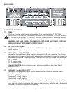


7. CHANNEL 1 ZONE ASSIGNMENT SWITCHES
Switches used to route the signal to the desired zone.
OPERATION NOTE: Anytime channel one is assigned to a zone and a signal is present in
channel one all other channels assigned to that zone will be ducked by 20 dB. This enables
channel one to be used for emergency override signals. This function can be disabled by
turning the threshold control completely counter-clockwise.
8. CHANNEL 2 ZONE ASSIGNMENT SWITCHES
Switches used to route the signal to the desired zone.
OPERATION NOTE: Anytime channel two is assigned to a zone and a signal is present in
channel two, all other channels assigned to that zone will be ducked by 20 dB (except
channel one). This function can be disabled by turning the threshold control completely
counter-clockwise.
9. CHANNEL 3 THRU 5 ZONE ASSIGNMENT SWITCHES
Switches used to route the background audio signal to the desired zone. Selecting a
particular zone button routes the audio source associated with that particular channel to the
desired zone. The zone assignment switches can be used to route the audio to one or more
zones if desired.
10. MASTER ZONE LEVEL CONTROLS
Controls the signal level being sent to each zone amplifier. Normally these controls should be
set at the 12:00 position and the overall system levels set using the various channel level
controls. This setting yields the best compromise for system noise performance and signal
headroom.
11. ZONE ACTIVE LEDS
Indicates whenever any signal activity is occurring in that particular zone. These LEDs will
light whenever a signal level above 50 mW RMS occurs in the associated zone power amp.
These indicators are helpful for setting up the zone signal levels.
12. ZONE CLIP LEDS
Indicates clipping may be occurring in that particular zone. These LEDs will light whenever a
signal level of 35 W RMS occurs in the associated zone. If these LEDs occasionally, flash
only on peaks of the music or paging signal, audible clipping is probably not occurring. If
these LEDs come on and stay on, then the power amps are clipping and audible distortion is
probably occurring in that zone.
OPERATION NOTE: These LEDs are only an indication of the level being sent to the power
amps from the preamp. If a signal processor is used in the insert point, it must be set up in a
way that it does not add/reduce the system gain. If the signal processor changes the signal
level between the preamp and power amp the LEDs are no longer accurate.
13. POWER SWITCH
Rocker type switch, depress to
Ò
onÓ position to power unit.
14. POWER LED
Indicates when AC power is being supplied to the unit and the power switch is ÒonÓ.
5