


yellow must be connected to the terminal which is marked by the letter E, or by the earth symbol, or
colored green or green and yellow. (2) The wire which is colored blue must be connected to the ter-
minal which is marked with the letter N, or the color black. (3) The wire which is colored brown must
be connected to the terminal which is marked with the letter L or color red.
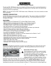
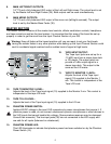
2. POWER:
This is the mixer’s main power switch. To turn the power on place the switch in the (|)
position. Place the switch in the (O) position to turn the power off. The power-on LED
indicator will light when the unit is on.
3. POWER LED:
This LED illuminates to indicate that power has been
applied to the unit.
INPUTS
AND OUTPUTS
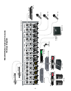
You must first connect your RQ to outboard equipment in order to better understand the remaining
functions. This section describes the inputs and outputs found on the rear of the RQ Series mixer.
The channel inputs are found in the “Input Channels” section of this manual in order to help you
understand the internal signal flow of your RQ mixer.
Warning: Always connect to the following jacks while the RQ and its associated equipment
are turned off. It is also recommended to turn the Master and Monitor Faders (see “Master
Section”) completely down before the unit is turned on to ensure that any signal being applied
to the RQ mixer is defeated before the outputs.
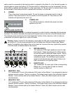
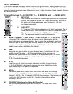
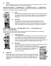
4. RETURN INPUTS:
1/4" balanced (TRS) high impedance input for high
level signals. These are designed for effect returns,
but can be used for additional stereo inputs. The tip
is the positive input, which should also be used for
unbalanced inputs. The Left/Mono input supplies
signal to both the left and right inputs if there is no
input connected to the right input jack.
5. EFFECTS OUT:
1/4" unbalanced TS output jack of the corresponding
Effects mix. It can be used to feed an external
monitor system or effect unit.
6. MONITOR 1 OUT:
1/4" unbalanced TS and a fully balanced XLR output of the Monitor 1 mix designed to feed an
external monitor system. (The tip is positive.) The output level is set by the individual channel
Monitor 1 send controls and by the master Monitor 1 fader (33). Both outputs can be used
simultaneously.
7. MONITOR 2 OUT:
1/4" unbalanced TS and a fully balanced XLR output of the Monitor 2 mix designed to feed an
external monitor system. (The tip is positive.) The output level is set by the individual channel
Monitor 2 send controls and by the master Monitor 2 fader (34). Both outputs can be used
simultaneously.
4
4
8
5
6
7
9
3