


5
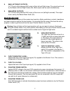
8. MAIN LEFT/RIGHT OUTPUTS:
1/4" TS and a fully balanced XLR output of the Left and Right mixes. The output level is set
by the Master Left and Right Faders (35). Both outputs can be used simultaneously.
9. MAIN MONO OUTPUTS:
1/4" TS and a fully balanced XLR output of the mono mix (left/right summed). The output
level is set by the Master Mono Fader (36).
MASTER SECTION
The Master Section contains all the master level controls, effects send/return controls, headphone
and tape controls as well as the level meters. It is important that this area of the board be set up
properly in order to get the most from the Input Channel Section of your RQ.
Warning: Keep all faders at the lowest position until you are ready to set your final levels.
Having the master faders in any other position while setting up the Input Channel Section could
result in accidental signal overload and/or sudden burst of signal at high levels.
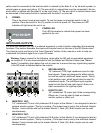
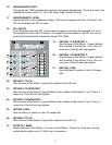
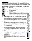
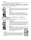
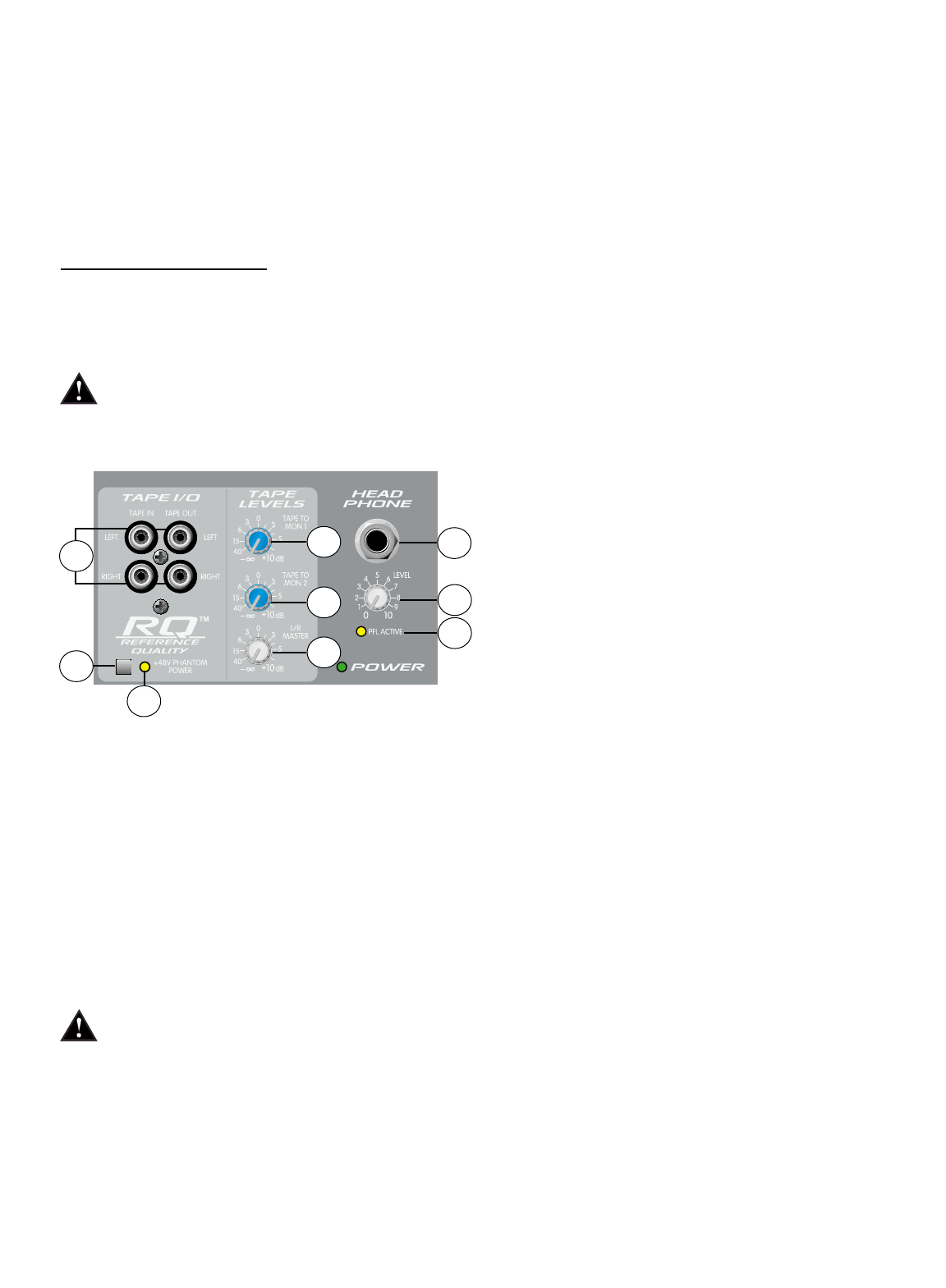
10. TAPE INPUT/OUTPUT:
The Tape Input jacks are set up for a
-10 dBV input from a stereo tape deck
or CD player. The output jacks can
provide a 0 dBu output signal to a
stereo tape deck. This output is the
same as the L/R mains.
11. TAPE TO MONITOR 1 LEVEL:
Adjusts the level of the Tape Input
signal (10) supplied to the Monitor 1
mix. This control is independent of the
Tape L/R Level.
12. TAPE TO MONITOR 2 LEVEL:
Adjusts the level of the Tape Input signal (10) supplied to the Monitor 2 mix. This control is
independent of the tape L/R level.
13. TAPE TO L/R LEVEL:
Adjusts the level of the Tape Input signal (10) supplied to the L/R mix.
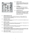
14. PHANTOM POWER SWITCH:
Applies 48VDC voltage to the input XLR connectors to power microphones that require it. If
phantom power is used, do not connect unbalanced dynamic microphones or other devices to
the XLR inputs that cannot handle this voltage. (Some wireless receivers may be damaged.
Consult their manuals.) The line input jacks (38) are not connected to the 48V supply and
are safe for all inputs (balanced or unbalanced).
15. PHANTOM POWER LED:
This LED illuminates to indicate that phantom power has been switched on by the Phantom
Power Switch (14).
10
14
15
11
16
17
18
12
13