


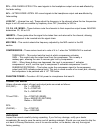
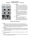
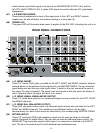

(8) MID FREQ
This control determines the center frequency of the MID control.
Center frequency for the bandpass filter can be set from 200 Hz
to 6 kHz.
(9) LOW
This active tone control is a shelving-type that varies low-frequency
response by +/-15 dB. Corner frequency is 75 Hz.
(10) AUX 1– 4
These controls adjust the level of the channel’s pre-fader signal that
is sent to the auxiliary mix. Gain is variable from minus infinity (– ∞)
to +10 dB. Unity gain is at the center detent position. Pre-fader
auxiliaries are typically used to send signal to stage monitors, but
can also be used to generate an independent recording mix.
NOTE: AUX SENDS 1-4 are factory set to deliver signal pre-EQ, but can
be modified (internally) to deliver signal post-EQ. Contact Peavey
Electronics Service Dept. for information. AUX SENDS 5-6 are always
post-EQ.
(11) AUX 5 – 6
These controls adjust the level of the channel’s post-fader signal
that is sent to the auxiliary mix. Gain is variable from minus infinity
(– ∞) to +10 dB. Unity gain is at the center detent position.
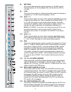
(12) PAN
This control determines the signal’s position with respect to L/R and
SUB 1– 4 outputs. Rotating the control counterclockwise increases
the amount of signal sent to L and odd-numbered SUBs; rotation
clockwise increases the amount sent to R and even-numbered
SUBs. For example, with the channel ASSIGN switch (13) in the
1/2 position, rotating the control counterclockwise increases the
amount of signal sent to SUB 1, while rotating clockwise increases
the amount sent to SUB 2. The C position sends equal amounts
to each.
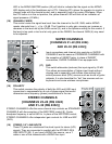
(13) 1/2, 3/4, L/R, MONO (ASSIGN)
These post-fader, post-EQ switches determine where the channel
signal is being sent. For example, to send a signal to SUBs 1 & 2,
depress the 1/2 button. The PAN control (12) determines how much
signal is sent to each SUB group.
(14) MUTE SWITCH/MUTE-CLIP LED
This switch mutes all AUX, SUB, L/R and MONO sends from the
corresponding channel. This switch is equipped with a red LED that
will illuminate when the channel is muted. When the MUTE switch is
disengaged, the LED functions as a clip (PK) indicator that will
illuminate at 2 dB below clipping. Muting the channel does not
prevent the PFL signal from being sent to the PFL mix when the
PFL switch (15) is engaged.
(15) PFL SWITCH/SIGNAL-PFL LED
This switch connects the channel’s pre-fader signal to the PFL mix.
With this feature engaged, the channel’s signal can be monitored
through the headphones and/or on the AFL/PFL display. A yellow
6
PAN
AUX
1
AUX
2
AUX
3
AUX
4
1
SIG/
PFL
MUTE/
PK
1
dB
10
0
5
3
3
40
15
6
dB
10
0
5
3
3
40
15
6
dB
10
0
5
3
3
40
15
6
dB
10
0
5
3
3
40
15
6
9
5
010
1
8
2
37
64
R
L
C
HI
GAIN
(dB)
CHANNEL
1/2 3/4
L/R MONO
PREPOST
EQUALIZATION
AUX
5
dB
10
0
5
3
3
40
15
6
AUX
6
dB
10
0
5
3
3
40
15
6
LOW
(dB)
12
0
1515
12
9
9
66
33
12
0
1515
12
9
9
66
33
10
6
3
0
6
12
30
20
300
150
20
10050
OFF
LOW
CUT
(Hz)
MID
(dB)
12
0
1515
12
9
9
66
33
MID
FREQ.
(Hz)
6K
2.5K
300
1K700
200
4
5
6
7
8
9
12
16
10
11
13
14
15