


6
<DRB1404>
En
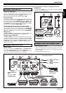
NAMES AND FUNCTIONS OF PARTS
MIC
HEADPHONES
POWER
MAXMIN
MASTER
CH-1 CH-2
HILOW
BPM
AUTO
TAP
PITCH
ERASE
BEAT
1
3
4
1
1
2
1
4
1
1
2
2
4
8
16
DELAY
1
2
MIC
MASTER
FILTER
ECHO
FLANGER
PHASER
ROBOT
ROLL
IN-LOOP
SAMPLER
CH. SELECT
LEVEL/DEPTH
ON/OFF
CD 1
+ 9
0
PHONO 1
/LINE 1
CD 2
PHONO 2
/LINE 2
2 CHANNEL DJ MIXER
TRIM
+ 9
HI
+ 9
MID
+ 9
LOW
+ 9
TRIM
+ 9
HI
+ 9
MID
+ 9
LOW
EQ
EQ
MASTER
LEVEL
OVER
4
2
00
-2
-4
-10
dB dB
OVER
4
2
-2
-4
-10
THRU
OFF TALK
OVER
MIC
MIC 1 LEVEL
MASTER
BEAT EFFECTS
0
LEVEL
0
MIC 2 LEVEL
0
FADER
START
FADER
START
LEVEL
PHONES
EQ
ON
BANK
BEAT
10
9
8
7
6
5
4
3
2
1
0
10
9
8
7
6
5
4
3
2
1
0
24
25
14
13
20
21
22
23
15
16
17
18
19
1
26
27
28
29
30
2
3
4 4
3
5 5
6
7
8
10
6
9
11
8
12
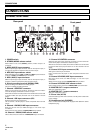
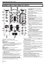
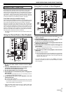
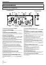
NAMES AND FUNCTIONS OF PARTS
1 Channel 1 input selector switch
CD 1:
The CD input connectors (line level input) are selected.
PHONO 1/LINE 1:
PHONO/LINE input connectors are selected.
¶ The connection panel’s PHONO/LINE switch is used to switch the
function of the channel 1 connectors between phonograph input
(analog turntable input) and line input (line level input).
2 Channel 2 input selector switch
CD 2:
The CD input connectors (line level input) are selected.
PHONO 2/LINE 2:
PHONO/LINE input connectors are selected.
¶ The connection panel’s PHONO/LINE switch is used to switch the
function of the channel 2 connectors between phonograph input
(analog turntable input) and line input (line level input).
3 TRIM adjust dial
Use to adjust the input level for each channel. (Adjustable range: –∞
to +9 dB, mid-position is about 0 dB)
4 Channel equalizer high-range adjust dial (HI)
Use to adjust the treble (high-range) frequency sound for each
channel (includes kill function). (Adjustable range: –∞ to +9 dB)
5 Channel equalizer mid-range adjust dial (MID)
Use to adjust the mid-range frequency sound for each channel
(includes kill function). (Adjustable range: –∞ to +9 dB)
6 Channel equalizer low-range adjust
dial (LOW)
Use to adjust the bass (low-range) frequency sound
for each channel (includes kill function). (Adjustable
range: –∞ to +9 dB)
7 Channel level indicators
Display the current level for each channel, with 0.6
second peak hold.
8 Channel fader levers
Use to adjust sound volumes for each channel.
(Adjustable range: –∞ to 0 dB)
9 Channel 1 fader start button/indicator
(FADER START)
Pressing this button toggles ON/OFF, the fader start/
back cue function for the DJ CD player connected to
channel 1. The button lights when set to ON. When
set to ON, the operation differs depending on the
setting of the cross fader selector switch.
¶ When the cross fader selector switch is at the left
(THRU) position, the function is linked to the
operation of the channel fader lever (not linked to
cross fader).
¶ When the cross fader selector switch is at the
middle ( ) or right ( ) position, the function is
linked to the cross fader lever (not linked to
channel fader).
10 Channel 2 fader start button/
indicator (FADER START)
Pressing this button toggles ON/OFF, the fader start/
back cue function for the DJ CD player connected to
channel 2. The button lights when set to ON. When
set to ON, the operation differs depending on the
setting of the cross fader selector switch.
¶ When the cross fader selector switch is at the left
(THRU) position, the function is linked to the
operation of the channel fader lever (not linked to
cross fader).
¶ When the cross fader selector switch is at the middle ( ) or right
( ) position, the function is linked to the cross fader lever (not
linked to channel fader).
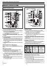
11 Cross fader selector switch
Select whether or not to use the cross fader, and to select from two
types of curve response.
¶ When the switch is set to left (THRU) position, the cross fader is
disabled, and the channel fader output is mixed without passing
through the cross fader.
¶ When this switch is set to the center ( ) position, the cross fader
is enabled, and a slowly rising curve response is selected.
¶ When set to the right position ( ), the cross fader is enabled, and
a rapidly rising curve response is selected (as soon as the lever
leaves the [< 1] side, the [2 >] sound is heard).
12 Cross fader lever
Outputs channel 1 and channel 2 sounds in accordance with cross
fader curve response selected with the cross fader selector switch.
The cross fader function is disabled when the cross fader selector
switch is set to the [THRU] position.
13 Master level indicators (MASTER LEVEL)
These indicators show the master output level in a monaural display.
Each indicator has a 0.6 second peak hold.
14 Master output level dial (MASTER LEVEL)
Use to adjust the master output level. (adjustable range: –∞ to 0 dB)