


USER’S GUIDE:
8
9
13
14
15
16
17
10
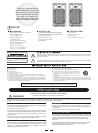
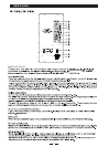
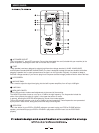
1 USB PORT
2 POWER INDICATOR
When the POWER SWITCH is turned on, and the line cord is connected to an active AC mains supply. This
indicator is just located above the LINE OUTPUT, glows to let you know that you're ready to rock and roll.
reduces the input signal. CLIP (LIMIT) led lights whenever the limit circuit is active.
It's okay for CLIP indicator to blink occasionally, but if it blinks frequently or continuously, either turn down
the signal level at the mixer or other signal source, or turn down the machine
3 MP3/IPOD SWITCH
4 CLIP INDICATOR
When signal levels at the amplifier outputs approach clipping, a soft limiting circuit is activated
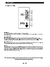
5 MASTR VOLUME
6 MP3/IPOD VOLUME CONTROL
7 MIC/LINE SWITCH
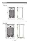
A combination XLR and 1/4” TRS connector, and accepts balanced or unbalanced line-level signals from
mixers, preamplifiers, CD players, tape decks.ect, with the MIC/LINE SWITCH out; and accepts direct
connections from dynamic microphones with the MIC/LINE SWITCH pushed in.
8 TAPE/CD INPUT( STEREO INPUT)
Channel 2 has a pair of RCA connectors, which accept a stereo line-level input from a CD player or TAPE
player (or any other line-level device)
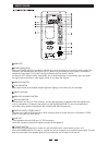
9 LINE OUT
These speakers has both XLR and 1/4” TRS connectors.
Use these connectors to patch the signal to another active speakers.
10 POWER SWITCH
Switch up to turn the machines on. Make sure the VOLUME control is down before you turn it on.
When the POWER SWITCH is turned on, and the line cord is connected to an active AC main supply. The cool
blue led on the back of the speaker glows to let you know that you're ready to rock and roll.
4
5
10
9
8
7
6
7