


2
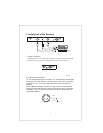
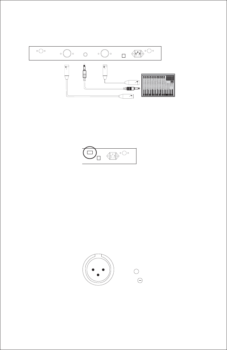
2. Installation of the Receiver
Fig. 3
Connect the AC power cable to the 110/220VAC jack (9) and the other end
into an AC outlet. Check the voltage selector (10) as shown in Fig. 4.
1. Power Connection
2. Audio Output Connection:
(A) 1/4” Unbalanced Output: Connect from the unbalanced
output jack (7) of the receiver the input jack of the amplifier,
as shown in Fig. 3.
(B) XLR Balanced Output: Connect an XLR cable from the balanced
output jack (8) of the receiver to the input jack of the mixer or amplifier,
as shown in Fig.3. There are two individual outputs corresponding to
the two microphones.
a 1/4” cable
to mixer or
This outputs the sound from both microphones
together.
ANT B ANT A
OUT B MIX OUT OUT A DC12
AC: 110V/220V 50/60Hz
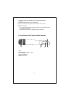
Fig. 4
ANT A
DC12
AC: 110/220V 50/60Hz
Fig.5
1:GND
2:HOT
3:COLD
12
3
+