


- 10 -
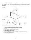
1 2 3 4 5 6 7 8
on
off
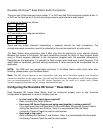
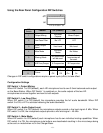
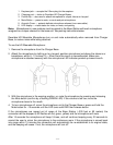
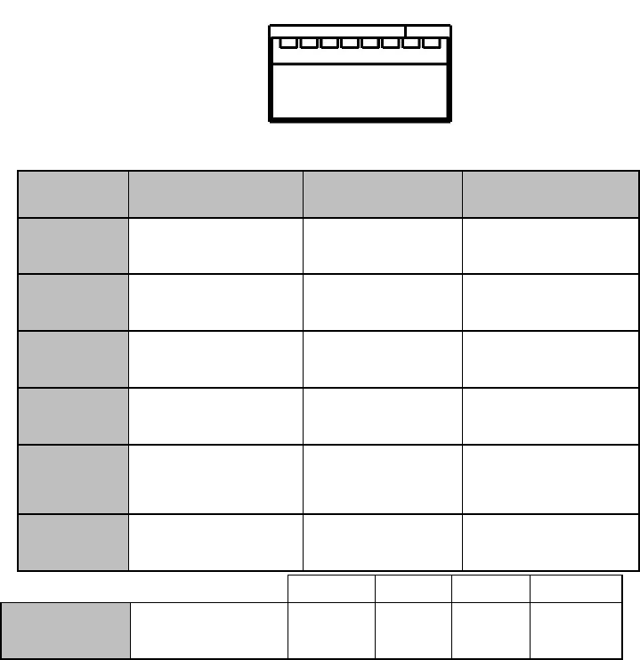
Using the Rear Panel Configuration DIP Switches
DIP
Switch
Feature
Off (Default)
On
1
Output Mixing
Individual
Outputs
Mixed Output
2
Low Pass Filter
No LPF
LPF
3
Audio Output
Level
Line Level
Mic Level
4
Mute Mode
Individual
Mutes
No Mutes
5
Sharing Mode
All frequencies
will be used.
Half of the
frequencies will
be used.
6
A/B Freq Groups
A Frequencies
B Frequencies
Changes in DIP switch configurations require a power cycle (off/on) to take effect.
Configuration Settings
DIP Switch 1- Output Mixing:
When DIP Switch 1 is OFF(default), each HD microphone has its own 3.5mm balanced audio output
on the Base Station. When DIP Switch 1 is switched on, the audio outputs of the two HD
microphones are mixed together and sent to both outputs.
DIP Switch 2 - Low Pass Filter:
When DIP switch 2 is OFF(default) the microphone provides the full audio bandwidth. When DIP
switch 3 is ON, a LPF is activated reducing the audio bandwidth.
DIP Switch 3 – Audio Output Level:
When DIP switch 3 is OFF(default) the microphone outputs provide a line level signal~0 dBu. When
DIP switch 3 is ON, the microphone outputs provide a mic level signal ~-40 dBu.
DIP Switch 4 - Mute Mode:
When DIP switch 4 is OFF(default) each microphone has its own individual muting capabilities. When
DIP switch 4 is ON, the microphone mute buttons are deactivated resulting in the mics always being
active and un-muted when not in the Charger Base.
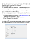
300'
150'
75'
25'
7
Transmit
Power
Off
On
Off
On
8
Off
Off
On
On