


- 9 -
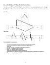
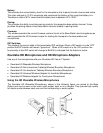
Revolabs HD Venue™ Base Station Audio Connections
There are two 3.5mm balanced inputs (either ¼‖ or XLR) and two 3.5mm balanced outputs (either ¼‖
or XLR) on the back panel of the unit providing access to each channel‘s audio signal.
¼‖ jacks are configured as follows:
Tip
positive
Ring
negative
Sleeve
ground
XLR connectors are configured as follows:
Pin 1
ground
Pin 2
positive
Pin 3
negative
There are two output channels representing a separate channel for each microphone. The
microphone output connectors need to be attached to the input connectors of an audio mixer.
The Base Station input connectors (also 0 dBu) may then be attached to mixer channel outputs.
Because the system is full-duplex, the input connections provide the ability to hear program audio
using a 2.5mm earpiece attached to the microphone (supplied with the wearable microphone).
Depending on the application, it is possible to feed a single audio feed back to each earpiece. This
would allow for translation, personal hearing assistance or other services to be incorporated into an
application.
NOTE: The USB port may exhibit static sensitivity. If the Base Station audio shuts down after
handling, please power cycle the Base Station
Note: The HD Venue System is not compatible with any other Revolabs system and therefore
cannot be installed in the same room. The HD and Solo Wireless Microphones and Charger Bases
are not interchangeable. Only two HD Venue Systems can be used in a single area. Please
contact support@revolabs.com for design recommendations.
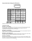
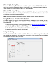
Configuring the Revolabs HD Venue
TM
Base Station
Each Revolabs HD Venue Base Station must be configured properly prior to use. Accurate
configuration is dependent on several variables such as:
Is Line Level or Mic Level signal required?
Refer to setting Dip Switch 3 below.
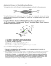
How many HD Venue Systems are being used together in close proximity?
If you have more than one Revolabs HD Venue Wireless Microphone System, refer to
setting Dip Switches 5 and 6 below. Note: It is recommended that the lowest
functioning Transmit Power be used for each system.
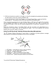
How large is the room?
Refer to setting Dip Switches 7 and 8 below. Note: It is recommended that the lowest
functioning Transmit Power be used for each system.