


FEB. 21,1980
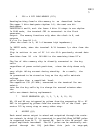
1 RS FLIP FLOP (2/4 IC3)
(a) PLAY Mode
When the START switch S5 is turned ON, the Q cutput goes to H and trig-
gers the Clock Generator (2). Mhen the STOP switch S6 is turned ON, the
Q output goes to L and the Clock Generator stops oscillation. At this
time, the Q output goes to H and resets the Binary Counter (5)
(b) WRITE Mode
The Q output goes to H when S5 is turned ON, and goes to L when S6 is
turned ON. This condition is written in the Memory IC1 as a data.
2 CLOCK GENERATOR (2/4 IC3)
The frequency of this oscillator is controlled with TEMPO VR-5. This
oscillator functions in PLAY mode only, and feeds clock pulses to the
Counter (5)
3 SCHIMITT TRIGGER (Q15, 17, 18)
This circuit functions in WRITE mode only. The collector of Ql5 goes
H when either the START switch S5 or the STOP switch S6 is turned ON,
and goes to L when the switch set to ON is turned OFF.
4 DELAY CIRCUIT (Q16)
The output from the Schmitt circuit (3) is intergrated, and fed to the
base of Q16. Then the signal is trimmed to square wave at collector of
Ql6. This output signal is differentiated and becomes pulses, and then
is applied to the R/~W terminal of IC1.
The two pulses lag a little behind edges of Scmitt (3) output pulse.
5 DUAL BINARY COUNTER (IC2)
This circuit counts pulses from the clock generator (2) in PLAY mode,
and counts pulses from the Schmitt trigger (3) in WRITE mode, and then
outputs binary-coded signals from the terminals Ql-Q5; Ql-Q4 denote 16
steps composing each rhythm. Signal from Q5 is applied to A7 only when
the VARIATION switch is set to AB.
To the terminal A7, the L level voltage is given when the switch is set
to A and H when switch is set to B.