


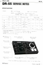


DR-5
5
6 256 x 4 BIT CMOS MEMORY (IC1)
Reading/writing from/to this memory is as described below.
The upper 3 bits designate rhythms 1-8, the next one bit
designates
VARIATION A and B, and. the lower 4 bits 16 steps in one rhythm.
In PLAY mode, the terminal CE2 is connected. to the Clock
generator
output. The memory functions only when the clock is H, and
outputs
H's or L’s from DO 1-4.
(When the clock is L, DO 1-4 becomes high impedance.)
In WRITE mode, when the terminal R/~W becomes L,a data from the
flip
flop is written in one of DI 1-4 via Sl.A previously stored data
is
rewritten from DO via R61-R64 to the remaining three DI's.
The Vcc of this rnemory chip is directly connected to the dry
cells
regardless of power switch positions, since the chip draws only
a
very slight idling current during stand-by. As a result, the
data
is guaranteed to be stored as long as the dry cells maintain
voltage
value higher than a specified. level.
The capacitor C39 (22 mfd.) connected to the terminal Vcc can
substi-
tute for the dry cells by its charge for several minutes when
the
cells are absent during replacement.
7 VOlCE GENERATOR (Ql, 2, 3, 7, 8, 9, 10, ll)
BD, SD and RS are triggered by pulses from the respective DO’s. HI
HAT is triggered by pulses from the counter IC2 or the Clock gen-
erator IC3 by every step or every other step.
8 ACCENT (Q3)
Each sound source output is mixed and outputted through the resis-
tor network in which Q3 is connected in parallel.When ACCENT pulse
is outputted from DO l, Q3 turned ON, and in this ON period the
signal amplitude increases. The DO l pulse can be externally out-
putted through the CSQ jack.When this jack is enga.ged,