


CHANNEL 1
MIC
TRIM
CHANNEL 2
MIC
TRIM
CHANNEL 3
MIC
TRIM
CHANNEL 4
MIC
TRIM
CHANNEL 5
MIC
TRIM
CHANNEL 6
MIC
LINE/
INSERT
TRIM
PHANTOM
POWER
MODEL RM65b
POWER
12 VAC
SERIAL NUMBER
65-
MADE IN U.S.A.
WARNING
:
DO NOT EXPOSE THIS EQUIPMENT TO RAIN
OR MOISTURE.
CAUTION:
TO REDUCE THE RISK OF ELECTRIC SHOCK DO NOT NOT REMOVE BACK.
NO USER SERVICABLE PARTS INSIDE. REFER SERVICING TO QUALIFIED SERVICE PERSONNEL.
RISQUE DE CHOC - NE PAS ENLEVER
LINE/
INSERT
LINE/
INSERT
LINE/
INSERT
LINE/
INSERT
LINE/
INSERT
STEREO
AUX BUSS
INPUT
FX
SEND
STEREO
FX RETURN
MONITOR
SEND
TRS STEREO
PLUG ONLY
TRS STEREO
PLUG ONLY
6 5 4 3 2 1
RIGHT
OUTPUT
LEFT
OUTPUT
VOLUME
RA170
PWR CLIP CLIP
MONITOR AMPLIFIER
WATTS
1 5 30 100
WATTS
1 5 30 100
VOLUME 1 VOLUME 1
PROTECT
0 10 0 10
MAINS AMPLIFIER
OPERATION
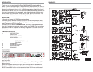
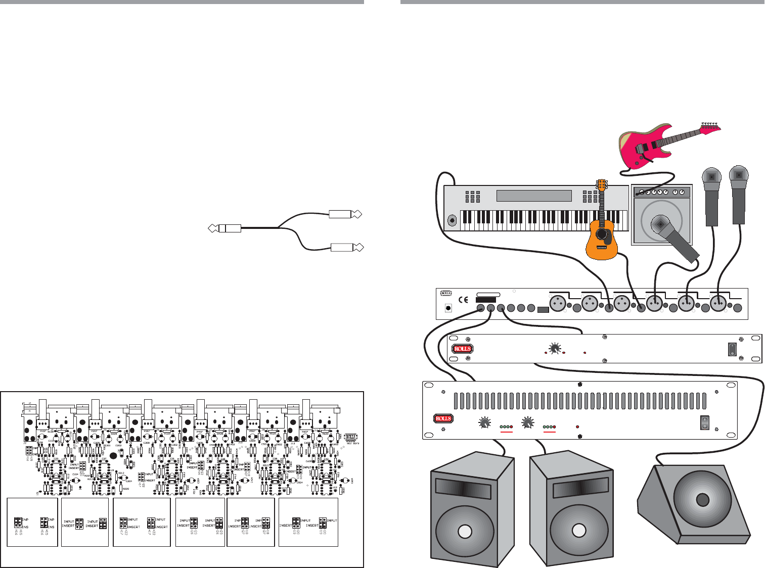
The RM65b is ideal for small combo groups where a small number of instruments and
microphones need to be mixed together. Refer to Figure 2 for an example of how to
connect the inputs and outputs of your RM65b. Connect microphones to balanced XLR
cables and to the XLR inputs. If any of these microphones are condenser microphones,
they will require phantom power. To turn on the phantom power for an individual channel,
set the phantom power switch for that channel to the ON (down) position. Instruments
may be played into a microphone which is connected as indicated above, or if you have
active pickups in your instrument, simply connect the output of your instrument to an
RM65b Line Input as the acoustic guitar is shown.
Electric guitars and basses normally are connected to an instrument preamplifier.
Amplifiers may have microphones placed in front of the speaker, or if the amp has a line
level output (check with the amplifier’s owners manual) - it may also be connected to the
mixer directly. Keyboards and sound modules are connected directly to the RM65b line
inputs as shown.
FX LOOP
To use the FX Loop, connect a 1/4” unbalanced cable to the FX Send and to the Input on
your signal processor or effects device. Connect the Outputs of the signal processor or
effects device to the RM65b FX Return jack. You will need an “Insert” type of cable (shown
to the rigth) to adapt the dual 1/4’ end connected
to your signal processor, to the 1/4’ TRS end of
the RM65b. The level of the effect will be con-
trolled by the settings on the channels’ FX Sends and by the Output
Level of your effects device, The overall level of the effect to the final mix
will be controlled by the FX Return level on the front of the RM65b.
MONITOR
To use the Monitor feature of the RM65b, connect the Monitor Out jack to a monitor
amplifier via a 1/4” unbalanced cable. Each channel’s monitor level is controlled by that
channel’s Monitor level setting. Be aware that the RM65b has no master monitor level, so
you will need to set the overall monitor level with the monitor amplifier and the Monitor
Levels of each channel.
Connect the Right and Left Main Outputs to the main amplifier(s) and make sure the
amplifier is the correct rating for the speakers. If you are operating in mono, use either the
Right or Left Output.
3 4
CHANNEL
6
CHANNEL
5
CHANNEL
4
CHANNEL
3
CHANNEL
2
CHANNEL
1
INPUT
INSERT
INPUT
INSERT
INPUT
INSERT
INPUT
INSERT
INPUT
INSERT
INPUT
INSERT
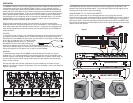
Figure 1
The RM65b may also be used for recording. Connect microphones, instruments, and
effects to the inputs as described above - the connect the Right and Left outputs to your
recording device and set the levels accordingly.
CONFIGURING THE 1/4” INPUTS AS INSERTS
NOTE: You are responsible for any damage that may occur during this process.
Carefully remove the seven screws that hold the lid of the RM65b to the chassis. Refer to
Figure 1 for the placement of the input to insert jumpers. To convert the 1/4” Input jack to
become an “Insert”, move the appropriate channel jumpers from INPUT to INSERT. Note
that channel 5 jumpers are moved perpendicular to their original placement for the Insert
position rather than parallel.
Figure 2