


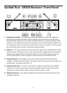
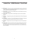
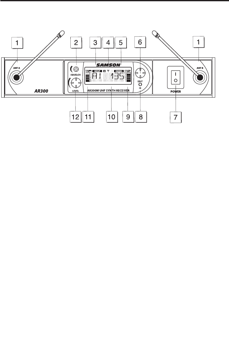
1. Antennas (A and B) - The antenna mountings allow full rotation for optimum
placement. In normal operation, both Antenna A (the antenna on the left) and
Antenna B (the antenna on the right) should be placed in a vertical position. Both
antennas can be folded inward for convenience when transporting the AR300. See
the “Setting Up and Using the AirLine Synth System” section on page 15 in this manual
for information about antenna installation and positioning.
2: Squelch – This control determines the maximum range of the AR300 before audio
signal dropout. Although it can be adjusted using the supplied plastic screwdriver,
it should normally be left at its factory setting. See the “Setting Up and Using the
AirLine Synth System” section on page 15 in this manual for more information.
3: Group Channel - This displays shows the current Group and Group Channel
number. A letter indicates Groups A through F and the Group Channel number are
indicated by 1 through 9 plus 0 for 10.
4: Antenna indicators – In order to maximize reception and distance, the AR300
implements true diversity receiver technology with dual RF strips. The A and B
antenna icon shows which of the receiver’s two RF strips is active.
5: Absolute Channel – This display indicates the specific channel number for each
available frequency.
Guided Tour - AR300 Receiver / Front Panel
4