


5
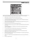
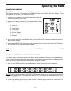
FRONT PANEL
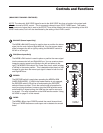
1 MIC/LINE – Combination Input connector for Low-Noise
Microphone pre-amp and Line level inputs.
2 GAIN – Used to set the input level of the mic pre and line
input.
3 CLIP – Red LED will illuminate indicating when the mic
GAIN has been adjusted too high.
4 HIGH FREQUENCY - Controls the high band of the
Channel Equalizer, +/- 15 dB at 12KHz.
5 MID FREQUENCY - Controls the mid band of the Channel
Equalizer, +/- 15 dB at 2.5KHz.
6 LOW FREQUENCY - Controls the low band of the Channel
Equalizer, +/- 15 dB at 80Hz.
7 LOW CUT – Bass roll off switch at 80Hz used to eliminate
unwanted low end rumble and hum.
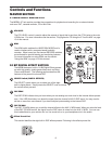
8 AUX 1/MONITOR – Pre fader auxiliary send that can be
used with an external effects processor, or to create a cue
or monitor mix.
9 AUX 2/DSP – Post fader auxiliary send connected to the
internal 24 BIT DSP effect processor and can also be
used with an external effects processor.
10 PAN – Controls the channel’s balance between left and
right in the stereo bus.
11 RECORD – Used in the HDM (HARD DISK MODE) to
assign the channel to the Record bus.
12 FADER – 60 mm audio taper fader provides smooth con-
trol over level changes.
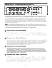
13 STEREO RIGHT LINE – Right Line Input connector on the
stereo channels.
14 STEREO MIC/LINE - Combination Input connector for Low-
Noise Microphone pre-amp and Left Line Inputs for the
stereo channels.
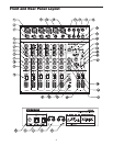
15 AUX 2– Output connector for Auxiliary 2.
16 AUX 1 - Output connector for Auxiliary 1.
17 CONTROL ROOM – Left and Right output connectors for
connecting a monitor system.
18 MIX – Left and Right main Mix output connectors.
19 MONO OUT – The Left and Right main Mix outputs are
summed together to a monaural signal and sent out this
connector.
20 MONO OUT LEVEL – Used to set the volume of the
MONO mix.
21 2TK LEVEL (2T TO MIX) - Level control used to mix
the 2 track input.
22 2 TRACK INPUTS & OUTPUTS – Connect a DAT,
Cassette, Mini Disk or Hard Disk Recording system.
23 HDM ( Hard Disk Mode) - Switch configures the mixer
for recording and overdubbing on a computer based
hard disk recording system.
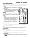
24 PHANTOM – Indicates that the 48 Volt Phantom
Power is on.
25 POWER – Indicates the MDR8 is powered up.
26 OUTPUT METER - Five segment display with VU bal-
listics indicates main Mix level.
27 DSP PEAK LED - LED light illuminates when the signal
sent to the internal DSP is clipped.
28 AUX 1 RETURN – Used to mix in level of the external
effects.
29 AUX 2 RETURN – Used to mix in level of the internal
DSP effects return.
30 SELECT - Used to switch between the 8 pre-sets of
the internal DSP effects processor.
31 2TRACK/MIX – Switches between the main Mix and
the 2 Track in the Control Room output.
32 C ROOM/HEADPHONE – Adjusts the volume of the
control room speakers or headphones.
33 HEADPHONE JACK – Connect stereo headphones
here.
34 MIX FADERS- Used to control the overall volume of
the Left and Right main Mix outputs.
REAR PANEL
A AC ADAPTER INLET – Connect External AC power
supply here.
B POWER – Switches on the MDR8’s main power.
C PHANTOM – Engages the 48-Volt Phantom power
supply to microphone pre- amps.
D AUX 1 RETURN – Connectors for stereo effects return.
E AUX 2 RETURN – Connectors for stereo effects return.
Front and Rear Panel Layout