


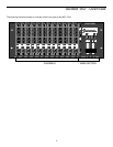
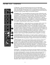
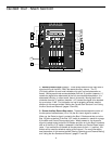
Guided Tour - Channels
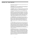
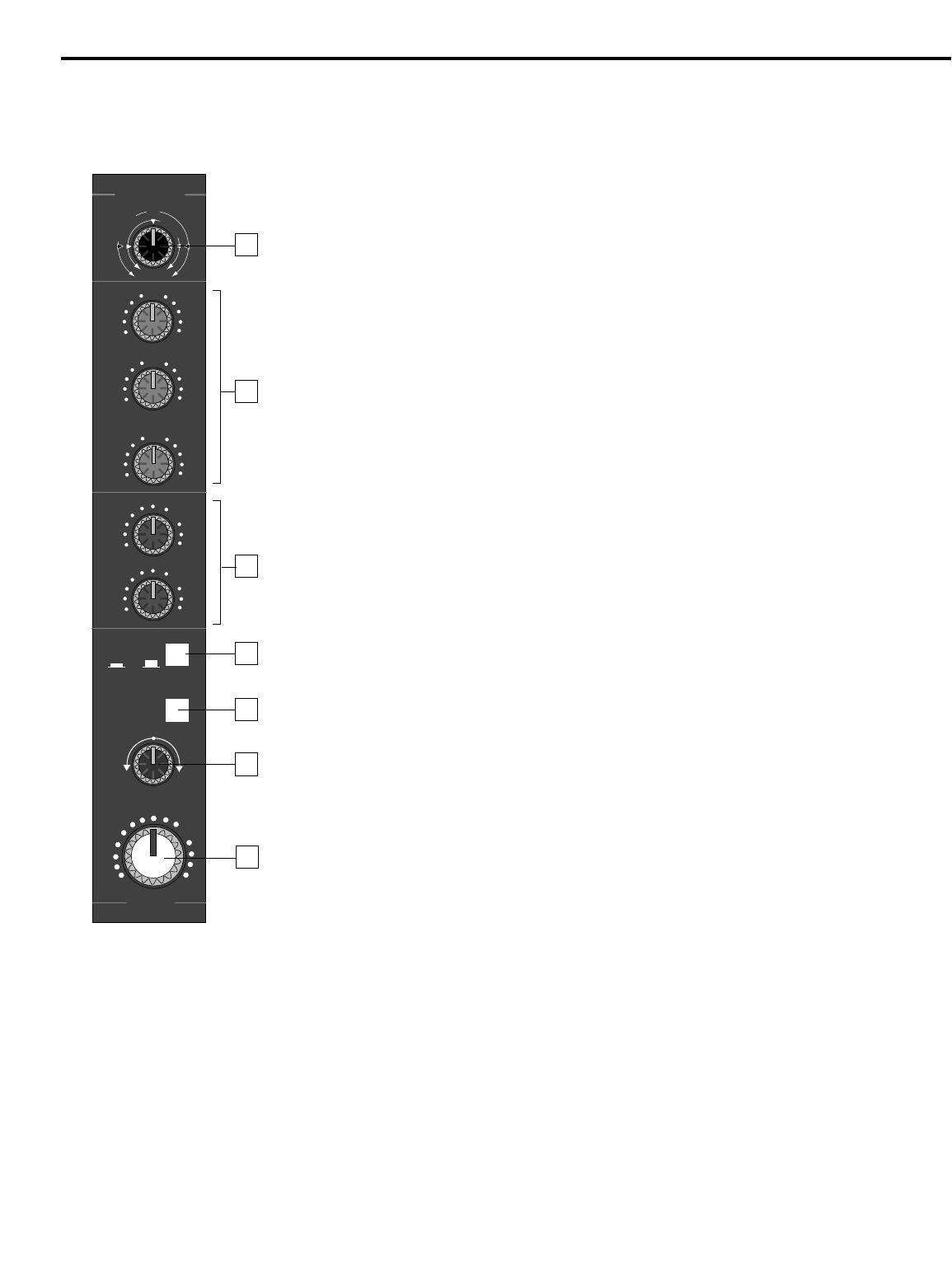
1: Trim (black) - This knob determines the input level of the connected signal.
Continuously adjustable from +4 dB to -50 dB (for mic inputs) or +24 to -30 dB (for line
inputs), the input signal is boosted when the trim is turned clockwise and attenuated when
turned counterclockwise. For information on how to properly set this for each channel, see
the section on page 14 entitled “Setting The Correct Gain Structure.”
2: Equalizer (violet) - These knobs determine the amount of boost or attenuation in each
of three frequency areas (up to 15 dB for low and high frequencies, and up to 12 dB for the
mid frequency). The mid frequency control (centered at 1 kHz) utilizes a resonant (“bell”)
peaking curve, while the high and low frequency controls (centered at 10 kHz and 100 Hz,
respectively) utilize shelving curves. A center detent in each knob (at the “0” position)
indicates no boost or attenuation (that is, flat response). As each knob is turned clockwise
from the “0” position, the frequency area is boosted; as it is turned counterclockwise from
the “0” position, the frequency area is attenuated. For more information on the application
of EQ, see the “Using Equalization” section on page 19 in this manual.
3: Auxiliary sends (blue) - These knobs allow you to route signal to either or both of the
MPL 1204’s two monophonic Auxiliary outputs. These are typically used to create
submixes (for example, a headphone cue mix) and to feed signal from single or multiple
channels to outboard effects devices. At the “0” (2 o’clock) position, the signal is routed
with unity gain (that is, no boost or attenuation). As each knob is turned clockwise from the
“0” position, the signal is boosted; as it is turned counterclockwise from the “0” position, it is
attenuated. Aux send 1 is post-eq but
pre-fade; that is, the level of the signal is determined
solely by its Trim control and its EQ settings (see #1 and #2 above). In contrast,
Aux send 2 is post-eq and
post-fade; that is, the level of the signal is determined by the
channel’s Trim control, its EQ settings, and the position of its Level control. For more
information, see the “Using Aux Sends and Returns” section on page 20 in this manual.
4: Solo On/Off switch - When pressed in, the channel is soloed (in headphones only).
Soloing will be in either PFL (Pre Fade Listen) or AFL (After Fade Listen) mode, depending
upon the setting of the PFL/AFL switch in the MPL 1204 main section. See #7 and #8 on
page 7 and the “PFL/AFL Soloing” section on page 22 in this manual for more information.
5: Mute 3/4 switch - When up, the channel’s signal is routed to the Bus 1/2 faders and
then on to the Bus 1/2 and, optionally, Main and Control Room output jacks (if, as
described in #14 on page 8, the Bus “L/R” switches for those buses is pressed in). When
pressed in, the channel’s signal is instead routed to the Bus 3/4 faders and then on to the
Bus 3/4 and, optionally, Main and Control Room output jacks (if, as described in #14 on
page 8, the Bus “L/R” switches for those buses is pressed in). If you set the Bus 3/4 faders
all the way down (to their “∞” position), this switch can be used for channel muting. See
the “Busing, Submixing and Channel Muting” section on page 17 in this manual for more
information.
6: Pan (green) - This knob allows you to place the input signal anywhere in the left-right
stereo spectrum, while keeping the overall signal level constant. When the knob is placed
at its center (detented) position, the signal is sent equally to both left and right outputs of
the selected bus (depending upon the setting of the channel’s Mute 3/4 switch, as
described in #5 above). When moved left of center, less signal is sent to the right output
and more signal is sent to the left output (making the sound appear left of center) and
when moved right of center, less signal is sent to the left output and more signal is sent to
the right output (making the sound appear right of center). To route a signal hard left or
right, place the pan knob either fully counterclockwise or fully clockwise. For more
information, see the “Using Pan” section on page 18 in this manual.
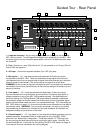
6
LEVEL
CH 1
0
M
I
C
TRIM
L
I
N
E
+4
+24
-30
-50
+4
+15
0
-15
HIGH
+12
0
-12
MID
+15
0
-15
LOW
∞
+10
0
∞
+10
0
AUX 1
AUX 2
PRE
POST
MUTE
3/4
SOLO
ON OFF
R
PAN
L
+10
∞
1
2
3
4
5
6
7