


8
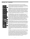
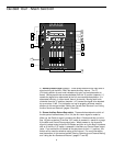
Guided Tour - Main Section
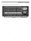
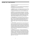
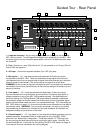
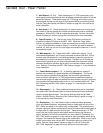
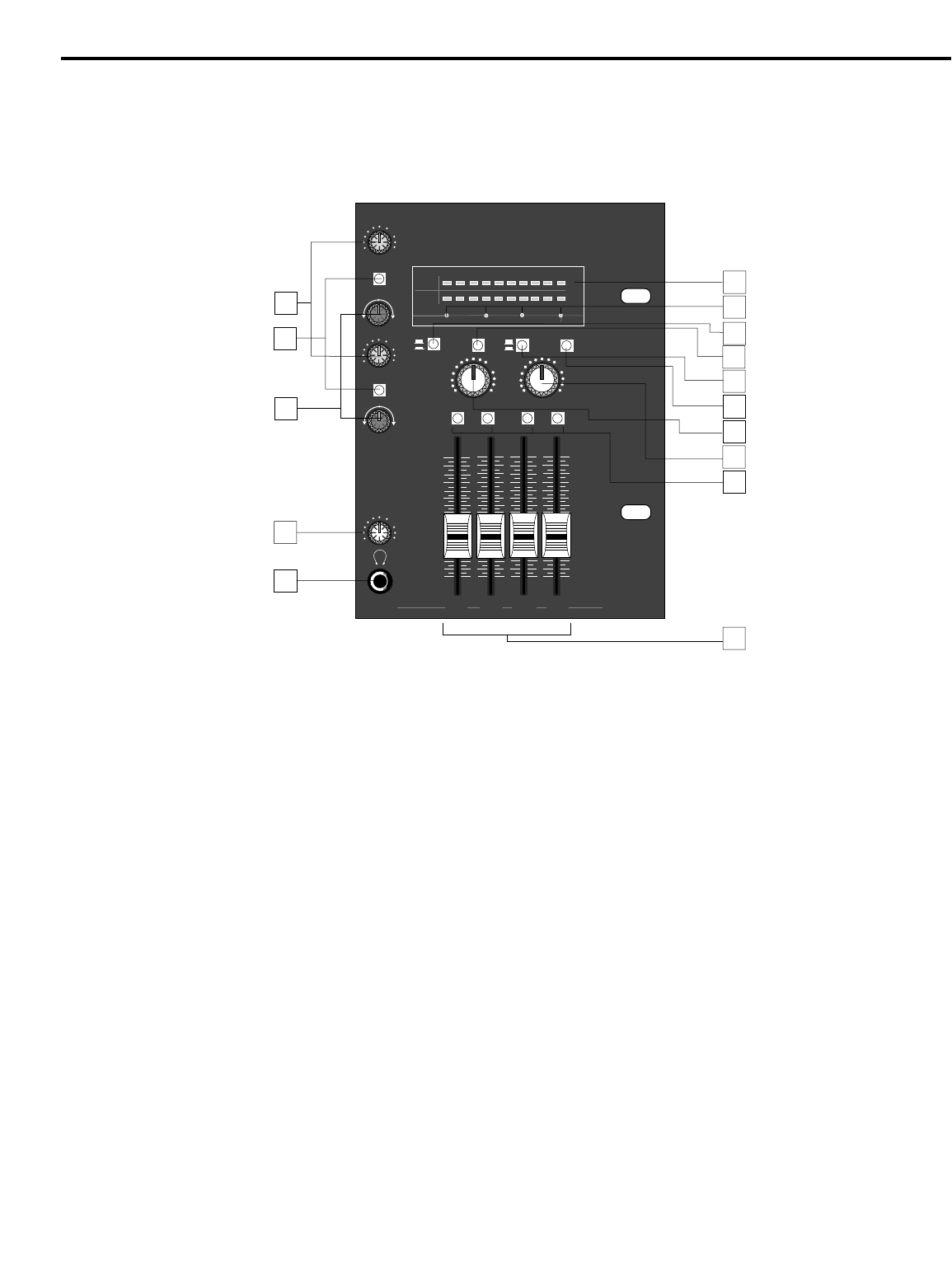
1: Auxiliary Return Level (orange) - These knobs determine the input level of
signal arriving via the MPL 1204’s two stereo Auxiliary returns. The “0”
(2 o’clock) position of each knob indicates unity gain (no level attenuation or
boost). Moving each knob counterclockwise from the “0” position (towards “∞”)
causes the signal to be attenuated (at the fully counterclockwise position, it is
attenuated infinitely—in other words, there is no sound). Moving each knob
clockwise from the “0” position (towards “+10”) causes the signal to be boosted
by as much as 10 dB. For information on how to properly set these, see the
sections in this manual entitled “Setting the Correct Gain Structure” and “Using
the Aux Sends and Returns” (pages 14 and 20).
2: Stereo Auxiliary Return Bus switch - These switches determine which of
the two pairs of stereo buses (1/2 or 3/4) the Aux return signal is routed to.
When up, the Return’s signal is routed to the Bus 1/2 faders and then on to the
Bus 1/2 jacks as well as (if the Bus “L/R” switch is pressed in—see #14 on page
8) the Main and Control Room output jacks. When pressed in, the channel’s
signal is instead routed to the Bus 3/4 faders and then on to the Bus 3/4 jacks as
well as (if the Bus “L/R” switch is pressed in) the Main and Control Room output
jacks. If you set the Bus 3/4 faders all the way down (to their “∞” position), this
switch can be used for selective muting of Aux returns. For more information,
see the sections in this manual entitled “Busing, Submixing and Channel Muting”
and “Using the Aux Sends and Returns” (pages 17 and 20).
MUTE
3/4
LEFT
RIGHT
-20
-15
-9 -6 -3
0+2+4+6
+8
PFL
AFL POWER
MAIN LEVEL
CONTROL ROOM
AUX RETURNS
STEREO
SAMSON
MPL 1204 MIC MIXER
AFL
PFL
L
R
L
R
BUS 2BUS 1 BUS 3
BUS 4
∞
∞
0
0
+10
dB
+10
dB
MUTE
3/4
-20
-15
-9 -6 -3
0+2+4+6
+8
SOLO
PHANTOM METER TAPE
11/12
1-2
3-4
+10
∞
+10
∞
1
2
5
8
7
9
10
11
12
PHANTOM
∞
+10
0
AUX RET.1/2
R
BALANCE
L
∞
+10
0
AUX RET.3/4
R
BALANCE
L
∞
+10
0
PHONES
3
4
6
13
14
15