


8
Operating The S gate 4
USING THE FILTERS
The S gate 4 employs a DFT (Dual Filter Trigger) circuit which allows you to create an equalization contour on
the trigger filter. The DTF is a two-stage, band-pass equalizer on the trigger or side-chain input. The filters are
applied to the trigger whether it is derived from the audio input, or by the KEY input. By using the DTF, you can
dial in and out the exact frequency range that you want to influence the opening and closing of the gate. This is
especially useful when gating drums, since you often have a lot of microphone bleed due to close placement and
the high SPL of the wood hitting the skin. By using the DFT, you can contour the trigger on each of S gate 4ʼs
channels to open the gate when it detects the frequency set on the High and Low Filter controls. Follow the steps
below to use the DFT to set the gate to turn a music track into a bass drum only track.
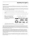
• Connect the first two channels of the S gate 4 to the main left and right insert points of your mixer. For a
detailed wiring guide see page 16 of this manual.
• Set both channelʼs controls to the default positions as described in the section "Setting Up the S gate 4".
• Press channel one and twoʼs IN/OUT switches to the IN position and engage the LINK switch.
• Play some music from a sound source (such as a CD player) into two channels of your mixer. For this
experiment you should use a recording with a contemporary, up-front drum track.
• Set the High filter control to the 9:00 position which is 250 Hz.
You should immediately hear the bass drum breaking through the gate. By engaging the filter you have
just created an EQ curve with a band pass of 30Hz to 250Hz on the gateʼs trigger detector. The result is
only the low energy from the kick drum will cause the gate to trigger open. You can use the TRIGGER,
ATTACK, HOLD and RELEASE to fine-tune and dial in just the sound of the kick drum.
Note:
You can hear the effect of the DFT circuit on the trigger or side-chain input by pressing the KEY
LISTEN switch. When engaged, the KEY LISTEN circuit routes the trigger signal to the audio output
allowing you to hear what effect the filters have on the side-chain.
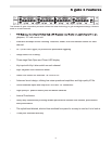
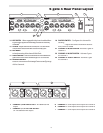
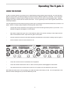
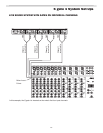
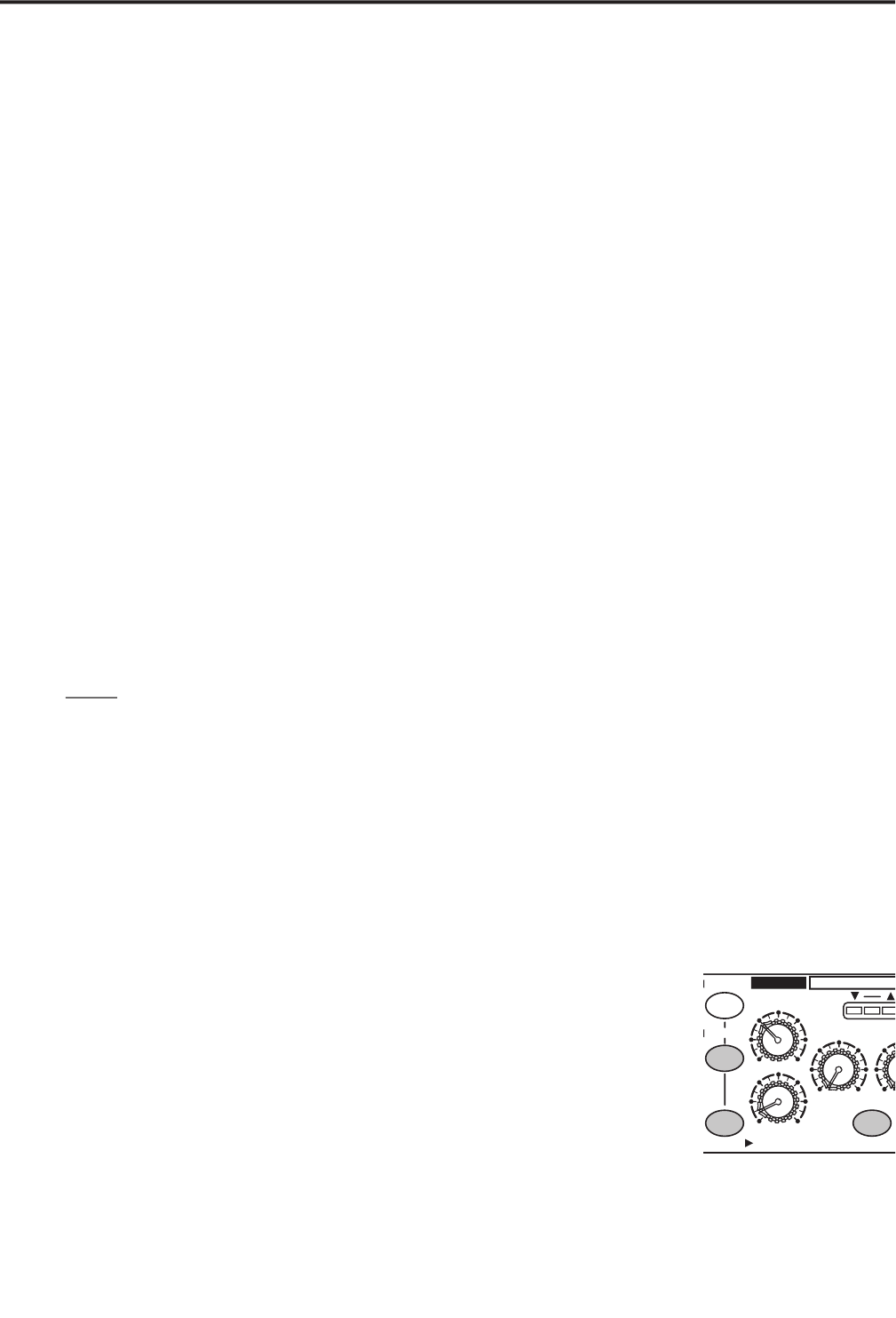
The example below shows a typical set up for using DFT while gating drum microphones.
POWER
1
RANG
E
ATTA
CK
RELEASE
dB
HOLD
TRIGGER
HIGH
LOW
LINK
KEY LISTEN
DUCKER
IN/OUT
IN/OUT
GAIN REDUCTION dB
30 24 1827 12 6 1 2
30
Hz
3K
.1
10
KHz
-50
+20
+4
dBu
mSec
Sec Sec
.3
300
20
.04
4
1
.5
.2
2
1
60
40
CH 1
1
RANG
E
ATTACK
RELEAS
E
dB
HOL
D
TRIGGE
R
HIGH
LO
W
KEY LISTEN
DUCKER
GAIN REDUCTION dB
30 24 1827 12
6 1 2
30
Hz
3K
.1
10
KHz
-50
+20
+4
dBu
mSec
Sec Sec
.3
300
20
.04
4
1
.5
.2
2
1
60
40
CH 2
1
RANG
E
ATTACK
RELEAS
E
dB
HOL
D
TRIGGE
R
HIGH
LO
W
LINK
KEY LISTEN
DUCKER
IN/OUT
IN/OUT
GAIN REDUCTION dB
30 24 1827 12
6 1 2
30
Hz
3K
.1
10
KHz
-50
+20
+4
dBu
mSec
Sec Sec
.3
300
20
.04
4
1
.5
.2
2
1
60
40
1
RANG
E
ATTACK
RELEAS
E
dB
HOLD
TRIGGE
R
HIGH
LO
W
KEY LISTEN
DUCKER
GAIN REDUCTION dB
30 24 1827 12
6 1 2
30
Hz
3K
.1
10
KHz
-50
+2 0
+4
dBu
mSec
Sec Sec
.3
300
20
.0
4
4
1
.5
.2
2
1
60
40
CH 4
KEY
KEY
KEY
KE
Y
CH 3
4 CHANNEL
EXPANDE
R
GATE
gate
Kick Drum with the filter
set on 30Hz and 200Hz.
Snare Drum with the filter
set on 1KHz and 2KHz.
Rack Tom with the fil-
ter set on 250Hz and
800Hz.
Floor Tom with the filter
set on 80Hz and 500Hz.