


5
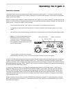
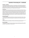
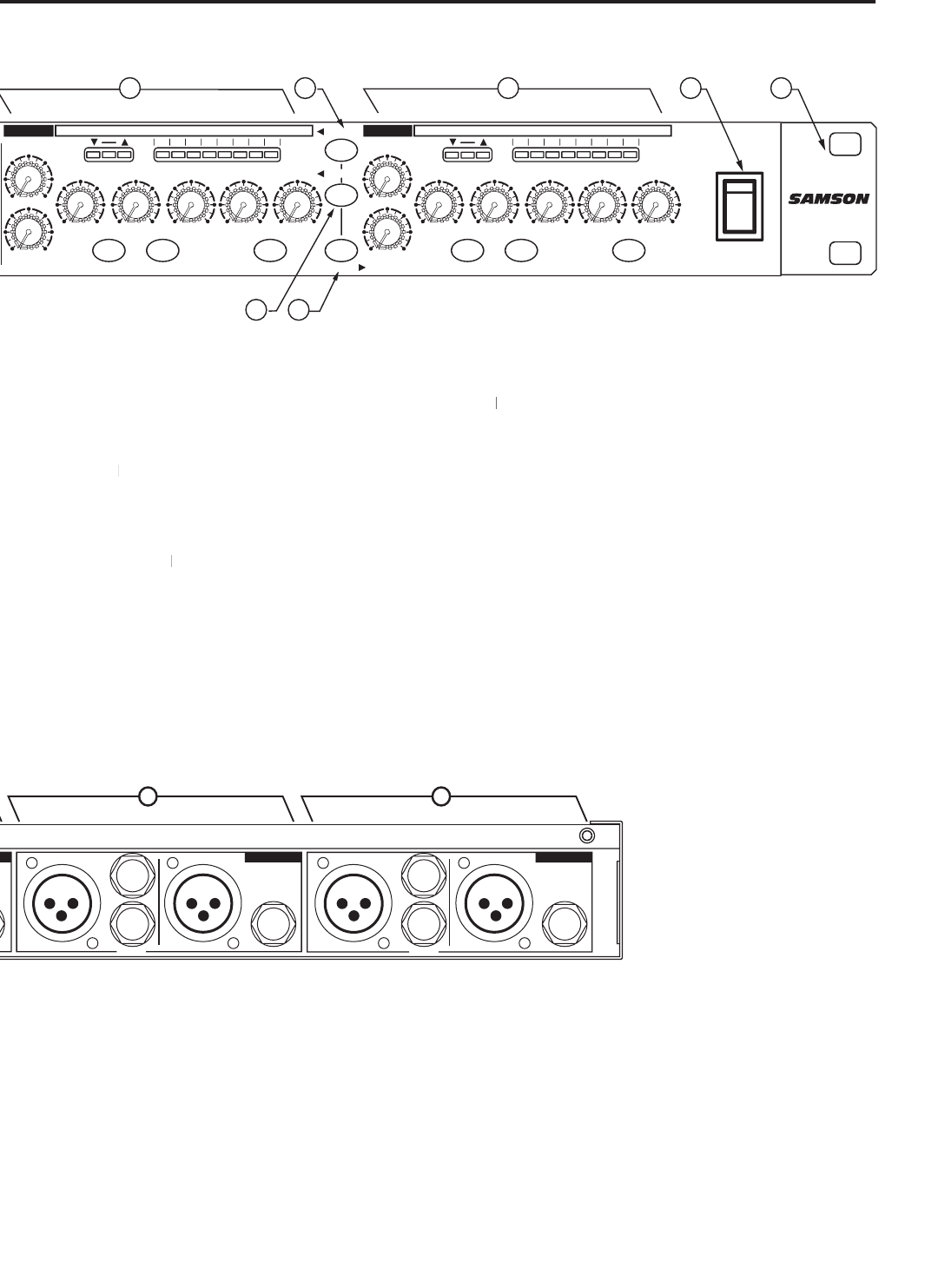
S gate 4 Rear Panel Layout
POWER
0
RANG
E
ATTACK
RELEAS
E
dB
HOLD
TRIGGE
R
HIGH
LO
W
LINK
KEY LISTEN
DUCKER
IN/OU
T
IN/OUT
GAIN REDUCTION dB
30 24 1827 12
6 1 2
30
Hz
3K
.1
10
KHz
-50
+20
+4
dBu
mSec
Sec Sec
.3
300
20
.07
4
1
.25
.02
5
1
100
40
CH 1
0
RANG
E
ATTA
CK
RELEAS
E
dB
HOLD
TRIGGE
R
HIGH
LOW
KEY LISTEN
DUCKER
GAIN REDUCTION dB
30 24 1827 12 6 1 2
30
Hz
3K
.1
10
KHz
-50
+20
+4
dBu
mSec
Sec Sec
.3
300
20
.01
4
1
.25
.02
5
1
100
40
CH 2CH 2
0
RANG
E
ATTA
CK
RELEAS
E
dB
HOLD
TRIGGE
R
HIGH
LOW
LINK
KEY LISTE
N
DUCKER
IN/OUT
IN/OUT
GAIN REDUCTION dB
30 24 1827 12
6 1 2
30
Hz
3K
.1
10
KHz
-50
+2
0
+4
dBu
mSec
Sec Sec
.3
300
20
.0
7
4
1
.25
.0
2
5
1
100
40
CH 3
0
RANG
E
ATTA
CK
RELEAS
E
dB
HOLD
TRIGGE
R
HIGH
LOW
KEY LISTEN
DUCKER
GAIN REDUCTION dB
30 24 1827 12
6 1 2
30
Hz
3K
.1
10
KHz
-50
+2
0
+4
dB
u
mSec
Sec Sec
.3
300
20
.0
1
4
1
.2
5
.0
2
5
1
100
40
CH 4
KEY
KE
Y
KE
Y
KE
Y
2
12
14
15 16 17
3
9
1
19
8
2018
23
5
7
4
10
11
21
22
6
13
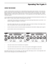
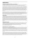
4 CHANNEL
EXPANDER
GATE
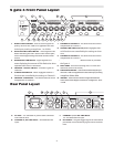
14 KEY SWITCH
– When engaged the Key insert is enabled allow-
ing the trigger signal to be externally processed or externally
controlled.
15 ATTACK -
Adjusts the amount of time, from .3 to 300 milisec-
onds, that the Gate/Ducker takes to become fully open.
16 KEY INSERT
– TRS Send and Return allowing for external con-
16 KEY INSERT– TRS Send and Return allowing for external con-16 KEY INSERT
trol and processing of the channel’s Side Chain.
17 HOLD CONTROL
- Used to set the amount of time before the
gate starts to close with a variable range of .01 to 4 seconds.
18 RELEASE CONTROL
- Adjusts the length of time the gate takes
18 RELEASE CONTROL - Adjusts the length of time the gate takes 18 RELEASE CONTROL
to return to the level set on the Range control covering a range
of .02 to 5 seconds.
19
DUCKER SWITCH
– Configures the channel for
Ducking.
20
RANGE
20 RANGE20
– Adjusts the level of maximum attenua-
tion, from 0 to 100dB.
21 CHANNEL 2 IN/OUT SWITCH
- Activates S gate 4’s
Channel 2.
22 CHANNEL 3 IN/OUT
SWITCH
- Activates S gate
4’s Channel 3.
23 CHANNEL 4 IN/OUT
SWITCH
- Activates S gate
4’s Channel 4.
KEY
INPUT
INPUT
INPUT
INPUT
KEY
KEY
KEY
CH 1
BALANCED
OUTPUT
CH 2
BALANCED
OUTPU
T
CH 3
BALANCED
OUTPUT
CH 4
BALANCED
OUTPUT
S
.
GA
TE 4
A
B ED
C F
G H I
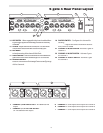
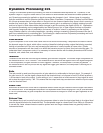
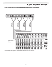
E CHANNEL 4, XLR LINE OUTPUT
- XLR Balanced line
output.
F CHANNEL 4, 1/4” TRS LINE OUTPUT
-
1/4” TRS Balanced line output.
G CHANNEL 3 -
Same Inputs and Outputs as Channel 4.
H CHANNEL 2 -
Same Inputs and Outputs as Channel 4.
I CHANNEL 1 -
Same Inputs and Outputs as Channel 4.