


9
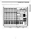
Guided Tour - Main Section
7: Tape In Level - Controls the level of signal arriving at the Tape Input jacks (see #1 on the preceding page).
8: Record Out Level - Controls the level of signal being output by the Record Out jacks (see #3 on the preceding page).
9: Auxiliary Return Level (1,2) - These knobs determine the input level of signal arriving via the TM500’s two stereo
Auxiliary return jacks (see #2 on the previous page). The “0” (2 o’clock) position of each knob indicates unity gain
(no level attenuation or boost). Moving each knob counterclockwise from the “0” position (towards “∞”) causes the signal
to be attenuated (at the fully counterclockwise position, it is attenuated infinitely—in other words, there is no sound).
Moving each knob clockwise from the “0” position (towards “+10”) causes the signal to be boosted by as much as 10 dB.
Note that, when the DSP On/Off switch (see #19 on the next page) is pressed in, the internal DSP signal is instead rout-
ed to Aux Return 2, with the Aux Return Level 2 knob controlling the amount of “wet,” processed signal. For
information on how to properly set these, see the sections in this manual entitled “Setting the Correct Gain Structure,”
“Using the Aux Sends and Returns” and “Using DSP” (pages 14, 20 and 22).
10: Auxiliary Send Level (1,2) - These knobs determine the output level of signal being routed to the TM500’s two
stereo Auxiliary Send jacks (see #6 on the preceding page) and, in the case of Aux Send 2, to the internal DSP (see the
“Using DSP” section on page 22 in this manual). The “0” (2 o’clock) position of each knob indicates unity gain (no level
attenuation or boost). Moving each knob counterclockwise from the “0” position (towards “∞”) causes the send signal to
be attenuated (at the fully counterclockwise position, it is attenuated infinitely—in other words, there is no signal being
sent). Moving each knob clockwise from the “0” position (towards “+10”) causes the send signal to be boosted by as
much as 10 dB. For information on how to properly set these, see the sections in this manual entitled “Setting the
Correct Gain Structure” and “Using the Aux Sends and Returns” (pages 14 and 20).
11: Meter - This ten-segment bar meter shows either the Left/Right output level or the Aux 1/2 Send level, depending
upon the setting of the Meter Headphone Source switch (see #15 below). For optimum signal-to-noise ratio, try to adjust
all left/right and Aux send levels so that program material is usually at or around 0 VU, with occasional but not steady
excursions to the red “+” segments. For more information, see the sections in this manual entitled “Setting the Correct
Gain Structure” and “Using the Aux Sends and Returns” (pages 14 and 20).
12: Power LED - Lights steadily green whenever the TM500 is powered on.
13: Phantom LED - Lights steadily red when the Phantom Power switch (see #14 below) is engaged.
14: Phantom Power switch - When this switch is pressed in, the TM500 delivers 48 volts of phantom power to pins
2 and 3 of all XLR microphone connectors in all eight monophonic channels. WARNING: Only use this switch with the
TM500 powered down. Before turning phantom power on, be sure to disconnect all non-microphone signal sources
(such as passive direct injection boxes) from the XLR mic jacks. Although phantom power will have no adverse affect
on connected dynamic microphones, it should be used only when one or more condenser microphones are connected to
the TM500.
Refer to the owners manual of your microphone to determine whether or not it requires 48 volts
phantom power—we cannot assume responsibility if you damage a mic by incorrectly applying phantom power.
If you’re not completely certain that one or more connected mics require 48 volts phantom power, leave this switch off (its
out position).
15: Meter / Headphone Source switch - When out (the “up” position), the Left/Right stereo output signal is routed to
the headphones jack (see #25 on the next page) and to the ten-segment meter (see #11 above). When pressed in, the
Aux send 1 and 2 output signals are routed to the headphones jack and to the ten-segment meter. Note that, whenever
any channel PFL switches are depressed (see #10 on page 5), the soloed channel(s) are instead routed to the
headphones jack (though not to the meter).
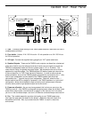
16: Rev To Aux 1 Level - This knob determines the level of signal being routed from the internal DSP to Aux Send 1.
It allows you to add reverb or other signal processing to the sound in onstage monitors or headphones connected to the
TM500 Aux Send 1 jack (when operating the TM500 in standard stereo configuration) or the right speaker outputs (when
operating the TM500 in “split mono” configuration; that is, when the Aux 1 / Monitor switch [see #20 on the next page] is
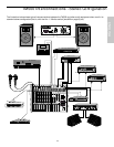
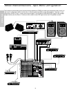
pressed in). For more information, refer to the wiring interconnection diagrams on pages 11 and 12 and to the sections
in this manual entitled “Using the Aux Sends and Returns” and “Using DSP” on pages 20 and 22.
ENGLISH