


10
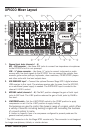
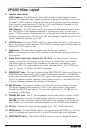
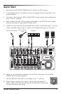
XP1000 Mixer Layout
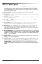
5. Equalizer control knobs
HIGH Frequency – The HIGH knob controls the amount of treble applied to each
channel. The channel’s high frequency response is flat when the knob is in the cen-
ter detent (12:00) position. Rotating the knob to the right will boost the channel’s
high frequency response above 10 kHz by 15 dB, and rotating it towards the left
will cut the high frequency response by 15 dB.
LOW Frequency – The LOW knob controls the amount of bass applied to each chan-
nel. The channel’s low frequency response is flat when the knob is in the center
detent (12:00) position. Rotating the knob to the right will boost the channel’s low
frequency response below 100 Hz by 15 dB, and rotating it towards the left will cut
the low frequency response by 15 dB.
6. EFFECTS switch - Use the EFFECTS switch to add an effect to a Mic or Line input on
any of the first four input channels. The EFFECTS indicator lights GREEN when the
channel EFFECTS switch is ON.
7. LEVEL knobs - This knob sets the overall level for the input channel.
NOTE: To reduce noise, set the LEVEL controls on any unused channels to the mini-
mum setting.
8. Stereo Channel Input Jacks (channels 5/6, 7/8, 9/10) - For stereo inputs, use the L
input to connect the left channel and the R input to connect the right channel.
Use these inputs to connect high impedance microphones, synthesizers, drum
machines, MP3, CD, tape players or any other line level device. The XP1000 fea-
tures ¼” phone,
¹
/
8
” phone, and RCA connectors.
9. MONITOR OUT jacks - The signal present at the MONITOR OUT jacks is sent from the
MONITOR level control knob, which is fed from the input channels. The MASTER
control does not affect the MONITOR OUT signal. This output can be used to send
the mix to powered speaker cabinets to use a stage monitors, or as additional front
of house speakers to expand the coverage of the system.
10. REC OUT jacks - This output is used to send the main mix to an external recorder.
The signal present at this connector is the L/R bus signal before it has passed
through the MASTER level control. The nominal output level is -10 dBV and the
impedance is 600 Ohms.
11. SPEAKER OUT jacks - Two ¼” phone powered output jacks used to connect the left
and right speakers. Use the included speaker cables to connect the speakers.
CAUTION: The total impedance load for each side of the amplifier must not be less
than 4 Ohms. Do not connect additional speakers to the XP1000 mixer/amplifier.
12. AC Input – Connect the supplied heavy-gauge 3-pin “IEC” power cable here.
13. POWER switch - Use the POWER switch to turn power to the XP1000 on or off. The
switch illuminates red when the unit is in the ON position and receiving power.
14. SPEECH/MUSIC switch - The SPEECH/MUSIC switch is used to change the overall