- 3 -
Ver. 6.0U _ Sep 6, 2012
Installation Manual for PV Modules
For grounding, each PV module has a hole in the frame for either a bolt,
nut and washer, a ground lug fastened by bolt or screw, or an appropriate
screw (hardware not provided). Installation for wiring and grounding
method shall be in accordance with national, regional and local codes,
laws, standard, and the relevant instructions below. In a connection of this
type, the hardware (such as a star washer) must score the frame surface
to make positive electrical contact with the frame. The ground wire must
not be smaller than No.12 AWG.
The National Electrical Code (NEC) 690.33 requires that connectors are
installed in a readily accessible location, circuits operating at over 30
volts, shall require a tool to open. PV module’s connectors comply with
the NEC corresponding section.
Grounding
(1) Grounding Using Existing Ground Hole (Figure 2, GBL-4DBT)
1. Place Grounding lug (GBL-4DBT, Ilsco corp, E34440) onto the frame,
making sure that the #8-32 or #10-32 ground bolt (Material; stainless
steel) straddles the grounding hole.
2. Thread the lock nut (Material; stainless steel) and tooth washer onto
the end of the bolt, tighten the nut. Recommended torque is between
2.0 and 2.2 Nm.
3. Insert the grounding wire into the lug. The grounding conductor wire
should be sized according to national, regional and local codes, laws,
and standards.
4. Fix the grounding wire by tightening the wire binding screw. This will
terminate the wire.
Please contact ”Ilsco corp.” about detail information of “GBL-4DBT”.
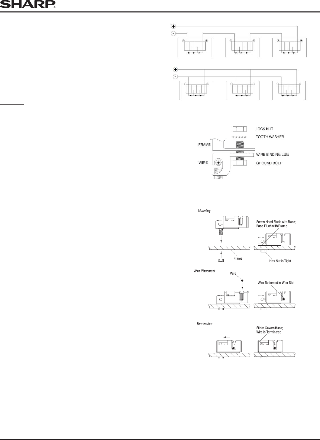
(2) Grounding Using Existing Ground Hole (Figure 3, 1954381-2)
The grounding clip (SolKlip grounding Clip Assemblies 1954381-2,
Tyco electronics corp., E69905) assembly consists of a slider, base and
#8-32 screw and hex nut (screw and hex nut are parts in component of
1954381-2).
1. Place the grounding onto the frame, making sure that the screw
straddles the grounding hole.
2. Thread the hex nut onto the end of the screw, tighten the nut.
Recommended torque is between 2.0 and 2.2 Nm.
3. Insert the grounding wire into the wire slot. Press down on both ends
of the wire (the wire slot will cause the wire to form a slight curve).
The grounding conductor wire should be sized according to national,
regional and local codes, laws, and standards. Note that the TYCO
SolKlip 1954381-2 only accepts wire sizes 10 -12 AWG.
4. Manually, or using channel lock pliers, push the slider over the base
until it covers the base. This will terminate the wire.
Please contact “Tyco electronics corp.” about detail information of
“1954381-2”
A-6. MAINTENANCE
SHARP PV modules are designed for long life and require very little
maintenance. If the angle of the PV module is 5 degrees or more, normal
rainfall is usually sufficient to keep the module glass surface clean under
most weather conditions. Do not touch the glass since finger prints or
stains will easily mark the glass. For AR coating - Sharp modules utilize
special materials to increase energy harvest. Always use gloves when
handling the module, never touch the glass with bare hands. If dirt build-
up becomes excessive, clean the glass surface with water only. If cleaning
the back of the module is required, take utmost care not to damage the
back side materials. In order to ensure proper operation of the system,
please check all wiring connections and the condition of the wire insulation
periodically.
SERIES WIRING (VOLTAGE ADDITIVE)
PARALLEL WIRING (CURRENT ADDITIVE)
Figure 1
Figure 1
Wire Binding Screw
Figure 2 (Ilsco, GBL-4DBT)
Figure 3 (Tyco Electronics Corp. 1954381-2)


