


- 6 -
Ver. 6.0U _ Sep 6, 2012
Installation Manual for PV Modules
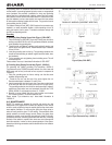
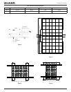
Mounting using Clamps on Long Edge of Module (Figure 7) – 2 Clamp Method
The modules may be mounted using clamps designed for solar modules as shown in Figure 7. Note the clamp position is important. The 22” length clamp
should be positioned so that it supports the center of each long frame of the solar module. The clamp should be affixed to the modules and mounting
structure with 4 bolts on each long frame. For the 2 clamp mount method, the minimum clamp length dimension is 22”. The modules should be inserted fully
into the module clamps so that the outside edge of the module frame is flush with the inside surface of the clamp. The clamp is designed to overhang the
top module edge by 12mm. This mounting method is designed to allow module loading of 1,440 Pa.
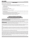
C) ELECTRICAL INFORMATION
ELECTRICAL RATINGS
Rated electrical characteristics are within ±10 percent of the indicated values of Isc, Voc and within +5/-0 percent of Pmax under Standard Test Conditions
(irradiance of 100 mW/cm2, AM 1.5 spectrum, and a cell temperature of 25˚C (77˚F)). The warranty conditions are specified elsewhere in this manual.
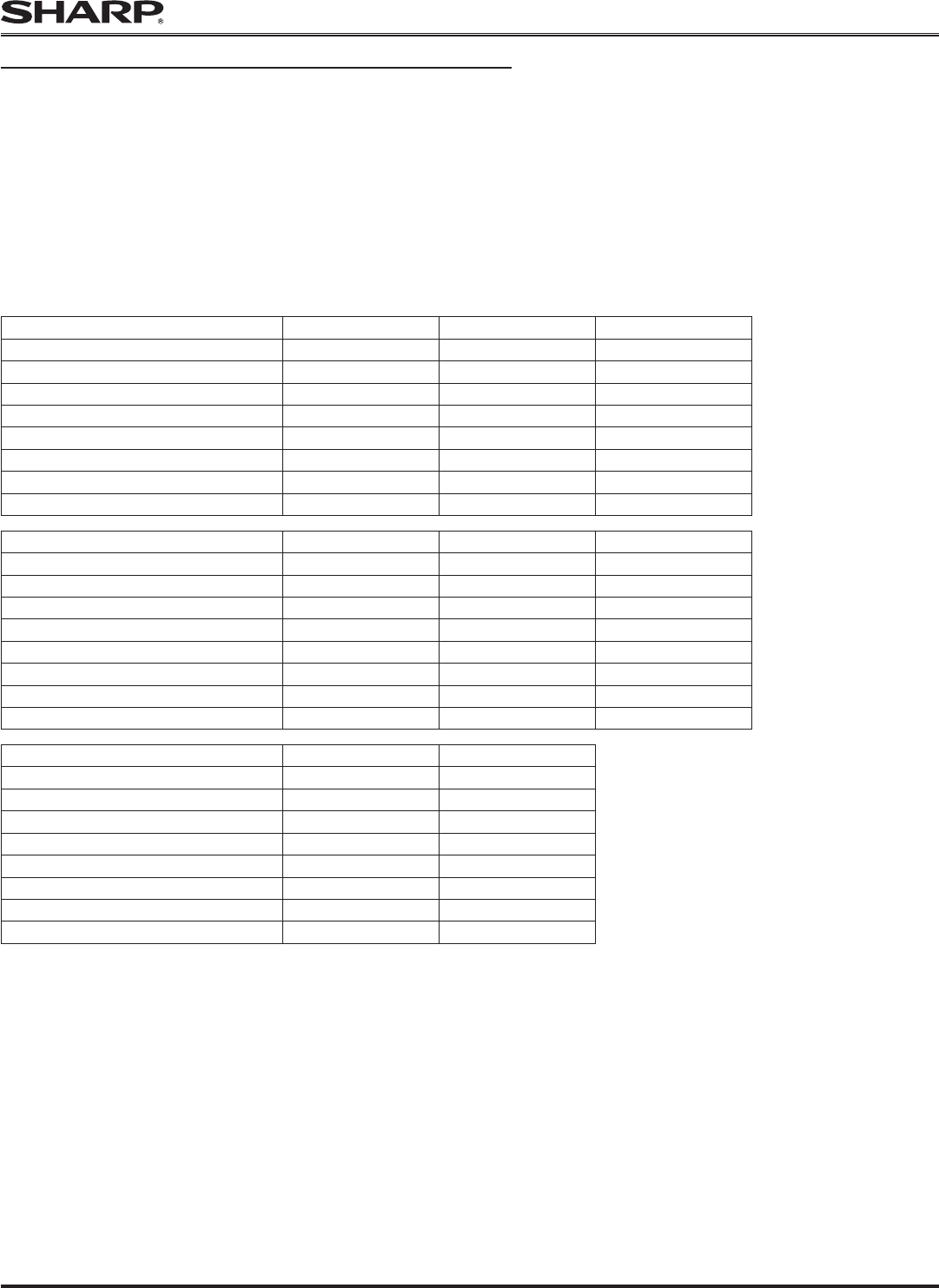
ND-255QCS ND-250QCS ND-245QCS
Maximum Power (Pmax) 255.0 W 250.0 W 245.0 W
Open-Circuit Voltage (Voc) 38.6 V 38.3 V 37.8 V
Short-Circuit Current (Isc) 9.0 A 8.9 A 8.9 A
Voltage at maximum power (Vpmax) 30.2 V 29.8 V 29.3 V
Current at maximum power (Ipmax) 8.45 A 8.4 A 8.36 A
Maximum System Voltage 600 V 600 V 600 V
Minimum Blocking diode 15 A 15 A 15 A
Series Fuse 15 A 15 A 15 A
ND-250QCJ ND-245QCJ ND-240QCJ
Maximum Power (Pmax) 250.0 W 245.0 W 240.0 W
Open-Circuit Voltage (Voc) 38.3 V 37.8 V 37.5 V
Short-Circuit Current (Isc) 8.9 A 8.90 A 8.75 A
Voltage at maximum power (Vpmax) 29.8 V 29.3 V 29.3 V
Current at maximum power (Ipmax) 8.4 A 8.36 A 8.19 A
Maximum System Voltage 600 V 600 V 600 V
Minimum Blocking diode 15 A 15 A 15 A
Series Fuse 15 A 15 A 15 A
ND-Q250F7 ND-Q245F7
Maximum Power (Pmax) 250.0 W 245.0 W
Open-Circuit Voltage (Voc) 38.3 V 37.8 V
Short-Circuit Current (Isc) 8.9 A 8.9 A
Voltage at maximum power (Vpmax) 29.8 V 29.3 V
Current at maximum power (Ipmax) 8.40 A 8.36 A
Maximum System Voltage 600 V 600 V
Minimum Blocking diode 15 A 15 A
Series Fuse 15 A 15 A
Under normal conditions, a PV module may produce more current and/or voltage than reported at Standard Test Conditions. Accordingly, the values of Isc
and Voc marked on UL 1703 listed modules should be multiplied by a factor of 1.25 when determining component voltage ratings, conductor ampacities, fuse
sizes and size of controls connected to the module output. Refer to Sec. 690-8 of the National Electrical Code for an additional multiplying factor of 125 percent
(80 percent de-rating) which may be applicable. Where Canadian UL listing applies, installation shall be in accordance with CSA C22.1, Safety Standard for
Electrical Installations, Canadian Electrical Code, Part 1.