


2
STAGE MONITOR & P.A. LOUDSPEAKER PLACEMENT
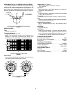
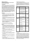
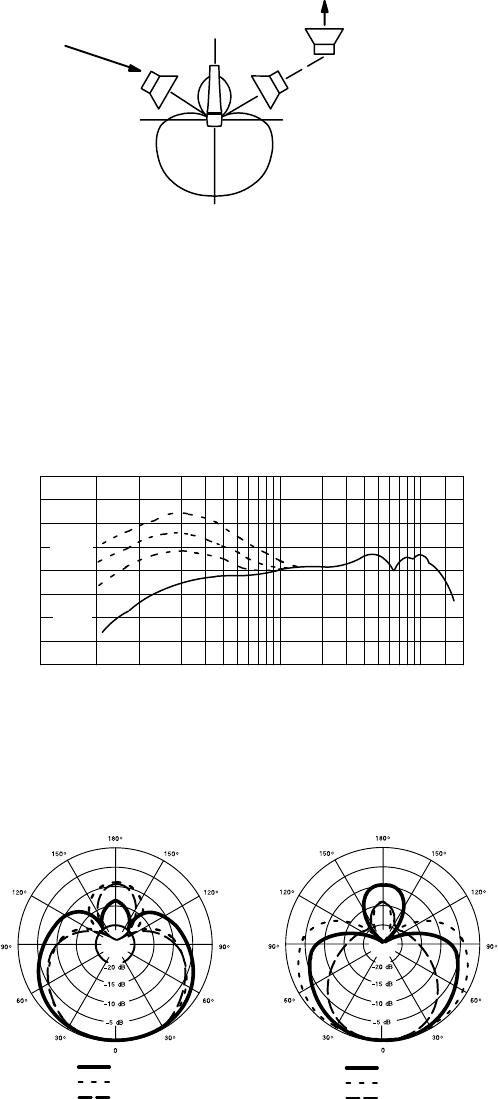
For maximum rejection of unwanted sound, place the stage
monitor or P.A. system loudspeaker at a 60° angle from the
rear of the Beta 57A, not directly behind it (see Figure 1). Al-
ways check out the stage setup before a performance to en-
sure that placement of microphone and monitors is optimum.
180°
120°120°
90°
0°
P.A. SYSTEM
LOUDSPEAKER
MONITOR
LOUDSPEAKER(S)
90°
RECOMMENDED LOUDSPEAKER LOCATIONS
FIGURE 1
SPECIFICATIONS
Type
Dynamic (moving coil)
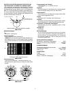
Frequency Response
50 to 16,000 Hz (see Figure 2)
NOTE: The curve below shows on–axis response at a
distance of 2 feet from a uniform sound source. Your
response may vary, depending on microphone position.
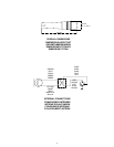
0.6 m
(2 FT)
51 mm
(2 IN.)
3 mm
(1/8 IN.)
25 mm
(1 IN.)
0
+10
–10
500 1,000 2,000 5,000 10,000 20,00050 100 20020
Hz
dB
TYPICAL FREQUENCY RESPONSE
FIGURE 2
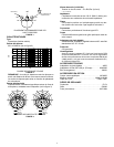
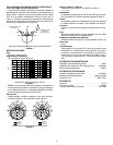
Polar Pattern
Supercardioid, rotationally symmetrical about microphone
axis, uniform with frequency (see Figure 3)
10000 Hz
6300 Hz
2500 Hz
1000 Hz
500 Hz
250 Hz
TYPICAL POLAR PATTERNS
FIGURE 3
Output Level (at 1,000 Hz)
Open Circuit Voltage –51 dBV/Pa* (2.8 mV)
*1 Pa = 94 dB SPL
Impedance
Rated impedance is 150 W (290 W actual) for connection to
microphone inputs rated low Z
Phasing
Positive pressure on diaphragm produces positive voltage
on pin 2 with respect to pin 3
Connector
Three-pin professional audio connector (male XLR type)
Case
Silver blue enamel–painted die cast metal with hardened,
matte-finished steel mesh grille
Adjustable Stand Adapter
Slip–in, adjustable through 180°, with standard 5/8”-27
thread
Net Weight
275 grams (9.6 oz)
Certification
Eligible to bear CE Marking. Conforms to European EMC Di-
rective 89/336/EEC. Meets applicable tests and performance
criteria in European Standard EN55103 (1996) parts 1 and 2,
for residential (E1) and light industrial (E2) environments.
FURNISHED ACCESSORIES
Adjustable Stand Adapter A25D. . . . . . . . . . . . . . . . . . . . . . .
5/8” to 3/8” (Euro) Thread Adapter 95A2050. . . . . . . . . . . . .
Storage Bag 26A21. . . . . . . . . . . . . . . . . . . . . . . . . . . . . . . . . . .
OPTIONAL ACCESSORIES
Locking Magnetic Windscreen A57AWS. . . . . . . . . . . . . . . .
Isolation Stand Mount A55M, A55HM. . . . . . . . . . . . . . . . . . .
7.6 m (25 ft.) Cable C25E, C25F. . . . . . . . . . . . . . . . . . . . . . .
REPLACEMENT PARTS
Cartridge R174. . . . . . . . . . . . . . . . . . . . . . . . . . . . . . . . . . . . . . .
Grille Assembly RK320. . . . . . . . . . . . . . . . . . . . . . . . . . . . . . .
Plug (Connector) Assembly 90F1984. . . . . . . . . . . . . . . . . . . .