


ENGLISH
ENGLISH
8
CONNECTING FP33 TRANSFORMER
BALANCED OUTPUTS TO TELEPHONE LINES
In the Line position, the Left and Right XLR outputs can be
used to drive dc-biased, “dialed up” telephone lines,
although there may be a slight increase in distortion. Use of
the limiter circuit is strongly advised, with the FP33 limiter
threshold set to +4 dBm. Modification of the FP33 output im-
pedance to 600: is recommended for proper fidelity. (See
the Internal Modifiable Functions section for instructions.)
When connecting the FP33 to a telephone line in the United
States, use of an FCC-Registered interface adapter between
the mixer and the telephone line is mandatory. Outside the
U.S., consult the local telecommunications authority.
USER ADJUSTMENTS
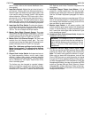
VU Meter Adjustment
To set the VU Meters to a value other than the factory
setting (0 VU = +4 dBm), proceed as follows:
1. Connect a 600 : load across the Left XLR output set
for Line.
2. Connect an ac voltmeter (such as the HP 400GL) in
parallel with the load.
3. Slide the 1 kHz tone oscillator switch to the On (up)
position.
4. Adjust the 1 kHz Tone Oscillator level with the Left
(inside) Master gain control until the ac voltmeter read-
ing is at the level desired.
5. Open the battery compartment door and adjust the
Left VU Level trim pot with a screwdriver until the Left
VU Meter reads 0.
6. Repeat the above procedure for the Right Output and
the Right VU Meter.
Limiter Threshold Adjustment
To adjust the Limiter threshold to a value other than the
factory setting (+15 dBm), proceed as follows:
1. Connect a 600 : load and an ac voltmeter across the
Left Line output as described in steps 1 and 2 of the
VU Meter Adjustment procedure.
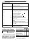
2. Open the battery compartment and move DIP switch
1 to the Off position (refer to the chart on the inside of
the door).
3. Slide the 1 kHz tone oscillator switch to the On (up)
position.
4. Slide the Limiter switch to the Off (down) position.
5. Adjust the Left Master gain control until the ac voltme-
ter reading is 2 dB above the desired output level.
6. Slide the Limiter switch to the On (LIM) position.
7. Open the battery compartment and adjust the Lim Adj
L trim pot until the level drops to the desired reading.
8. Repeat the above procedure for the Right output, us-
ing the Lim Adj R trim pot.
Peak LED Adjustment
To adjust the Peak LED threshold to a value other than
the factory setting (+17 dBm), proceed as follows:
1. Connect a 600 : load and an ac voltmeter across the
Left Line output as described in steps 1 and 2 of the
VU Meter Adjustment procedure.
2. Slide the 1 kHz tone oscillator switch to the On (up)
position.
3. Slide the Limiter switch to the Off (down) position.
4. Adjust the Left Master gain control until the ac voltme-
ter reading is at the desired peak output level.
5. Open the battery compartment and turn the Peak LED
L trim pot completely clockwise.
6. Slowly adjust the trim pot counterclockwise until the
left Peak/Lim LED first illuminates red.
7. Repeat the above procedure for the right Peak/Lim
LED, using the Peak LED R trim pot.
Headphone Level Adjustments
To adjust the program level to match the audio signal
levels from a monitored source, proceed as follows:
1. Open the battery compartment and adjust the Head-
phone Level L and Headphone Level R ful counterclock-
wise.
2. Connect the device to be monitored via the 3.5 mm
Monitor In jack.
3. Move the Monitor Input Switch on the front panel to the
locking position (left).
4. Adjust the monitor input level, using the headphone
gain control on the front panel.
5. Move the Monitor Input switch on the front panel to the
post-master audio position (center).
6. Adjust the post-master audio to a comparable level,
using the Headphone Level L and Headphone Level
R potentiometers.
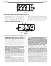
INTERNAL MODIFIABLE FUNCTIONS
Selected internal functions of the FP33 can be modified
by the user to fit special applications. Procedures for per-
forming these modifications are listed below.
CAUTION: Due to the complex construction and exten-
sive use of surface-mount components, modifications to
the FP33 must be performed by a qualified service techni-
cian. Contact the Shure Service Department or your au-
thorized Shure Service Center for further information on
these modifications.
Disassembly
1. Remove the six screws that secure the cover.
2. Slowly slide the cover backwards and unplug ribbon
cable P109.
3. Remove the three screws (marked with arrows) that
secure the upper PC board.
4. Remove the upper PC board.
5. Perform the appropriate modification procedure.
6. Reassemble the unit by doing Steps 1–4 in reverse.
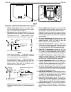
Changing the Line Level Output Impedance to 600 :
1. Locate R674 and R668 on the bottom PC board and
remove them.
2. Locate X503 and X505 on the bottom PC board and sol-
der a 470 : 1/2W resistor through the holes at X503.
3. Solder a 470 : 1/2W resistor through the holes at
X505.
Changing the Tape Out Jack from Stereo (tip = L;
ring = R) to Mono (tip = L+R; ring = L+R)
1. Locate X504 on the top side of the lower PC board, by
the Tape Out jack.
2. Solder a jumper through the holes at X504.