


2
the output level of both left and right channels. Note that the head-
phones output level is high enough for use as an auxiliary unbal-
anced line feed to drive a tape deck or a power amplifier.
Input 1–4 XLR Connectors: are balanced, professional, three-pin
audio connectors. Pins 2 and 3 are “hot,” and pin 1 is ground. For
microphone operation, the Input Mic/Line switches must be in the
Mic position; for line level inputs, the switches must be in the Line
position. Phantom Off/On Slide Switch: controls the application of
phantom power for condenser microphones to all inputs. With the
switch on and Input Mic/Line switches in the Mic position, +30 Vdc
is applied to pins 2 and 3 of each input connector. Series current-
limiting resistance is 3.3 kilohms for each input. When using other
than Shure condenser microphones, verify that the voltage and re-
sistance requirements are compatible.
Output L and R XLR Connectors: are professional, three-pin au-
dio connectors for connection to either low-impedance microphone
or line-level inputs of power amplifiers, mixers, or other signal-proc-
essing equipment. The Output Mic/Line switch selects either mi-
crophone- or line-level output signals.
Mix Bus L and R Phono Pin Jacks: provide direct access to the
left and right output channel mixing buses. This facilitates stacking
or “multing” FP42s to achieve additional input capacity without los-
ing any inputs. With two FP42s connected at their mix bus jacks, for
example, the left and right mix buses of each unit are directly con-
nected, providing two independent (ganged) master gain controls
and two isolated line amplifiers with eight individually controlled in-
puts. Since the buses are directly connected, a 6 db drop in the gain
of each output channel will occur, and the master or input controls
must be increased to compensate.
INSTALLATION AND OPERATION
Battery Operation
In addition to 120- or 240-volt ac operation, the FP42 can be oper-
ated from an internal battery pack. Current drain is typically 32 mA
at + 4 dBm output level. Battery operation is recommended for re-
mote, on-location operation, and as an emergency backup source
in case of ac power failure.
Access to the battery compartment is through the bottom of the
chassis. Three 9-volt transistor radio batteries power the FP42 at
full rated output. Use alkaline batteries for maximum life. Battery life
is approximately 10 hours at +4 dBm continuous use. Note that
phantom power loading will increase battery drain.
With batteries in the battery compartment, the FP42 will automati-
cally and silently switch to battery operation should the ac voltage
fall below a suitable level.
Battery condition can be determined by using the Batt Check switch
on the front panel. With the FP42 power switch on, activate the Batt
Check switch, and observe the VU meter. A new set of batteries will
give about a +2 VU indication. Battery condition is good if the read-
ing is above 0 VU; a lower reading means that new batteries are
required for proper operation. (Note that the FP42 power switch
must be turned on to check battery condition.)
Connections
Connect the signal sources to the three-socket XLR Input connec-
tors and set the Mic/Line switches for the proper level. Connect the
three-pin XLR Output L and R connectors to low-impedance micro-
phone or line-level inputs of power amplifiers, mixers, VTRs, etc.
Set the Output Mic/Line switch for the appropriate signal level.
If desired, connect additional FP42s or other mixers using the Mix
Bus phono pin jacks. A common ground connection can be estab-
lished using the rear-panel Ground binding post.
Connect the line cord to a 120 Vac +10%, 50/60 Hz source if the
FP42 is to be ac-operated. If 240-volt ac operation is desired, refer
to the Service section.
Adjustments
Turn the Power switch to the On position (VU meters will light in ac
operation). Turn the Phantom switch on if non-battery-operated
condenser microphones are to be used with the FP42. (Caution: Do
not turn the Phantom switch on when using unbalanced low-imped-
ance microphones; objectionable hum will result.) Note that phan-
tom power cannot be applied to the inputs with the Mic/Line
switches in the Line position; if line-level condenser microphones
(such as Shure’s SM82) are to be operated on phantom power,
contact Shure’s Customer Services Department for modification in-
structions.
Turn the Limiter switch to Out. For each input channel, apply an in-
put signal and rotate the associated Pan control to assign the signal
to the left or right output channel as desired. Adjust the Channel
Level control for each channel so that the VU meter needles move
with the audio signals in the 0 VU to –20 VU range, with occasional
movement into the 0 VU to +3 VU (red) area. With the limiter out, the
red Peak/Limiter LEDs will flicker as the signal level approaches
clipping.
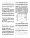
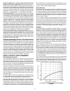
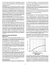
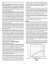
If desired, activate the Lo Cut Filter switches above the Channel
Level controls. The filter action will help reduce wind noise and un-
desirable low-frequency signals such as from condenser micro-
phones or turntable rumble (see Figure 1).
LO-CUT FILTER ACTION
FIGURE 1
Note that each input Channel Level control has a cuing capability.
To cue a channel while the other channels are carrying program
material, pull the desired channel Level control outward to the cue
position. This removes that channel from the mixing circuitry and
routes it only to the Headphones jacks. Adjust the Headphones lev-
el control to a comfortable listening level, and adjust the cued chan-
nel Level control for a proper mixing level. Restore the cued signal
to the program mix by pushing the Channel Level control inward.
The limiter circuit is activated by the Limiter switch. With the switch
set to In, mixer output is limited to the preset threshold level of +14
dBm. Increasing the Channel Level or Master gain controls in-
creases the average output and the amount of limiting. To adjust the
limiter threshold, refer to the Service section.
With the limiter circuit in, the Peak/Limiter LEDs light to show limiter
action. The LEDs respond much faster than VU meters and are ac-
tivated by extremely short transient peaks, but remain on long
enough for easy recognition.
VU Meter
The VU meters are factory-calibrated for use with a 600-ohm termi-
nated line. The VU Range switch on the rear panel selects either a
+4 or +8 dBm output at 0 VU meter indication. (This switch changes
the meter indication but does not change the actual output level.)
Microphone output levels are 50 dB below line output. The +4 range