3
Front Panel Controls, Connectors, and Indicators
1 2
L C R L C R TAPE RTNSLATE
1kHz
METER
L
R
–30 –15
0 +4 +8 +12
+16
INT EXTPHONES
POWER
MIC
FP24
3
4
5
6
78
910 11
12
13
12
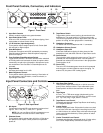
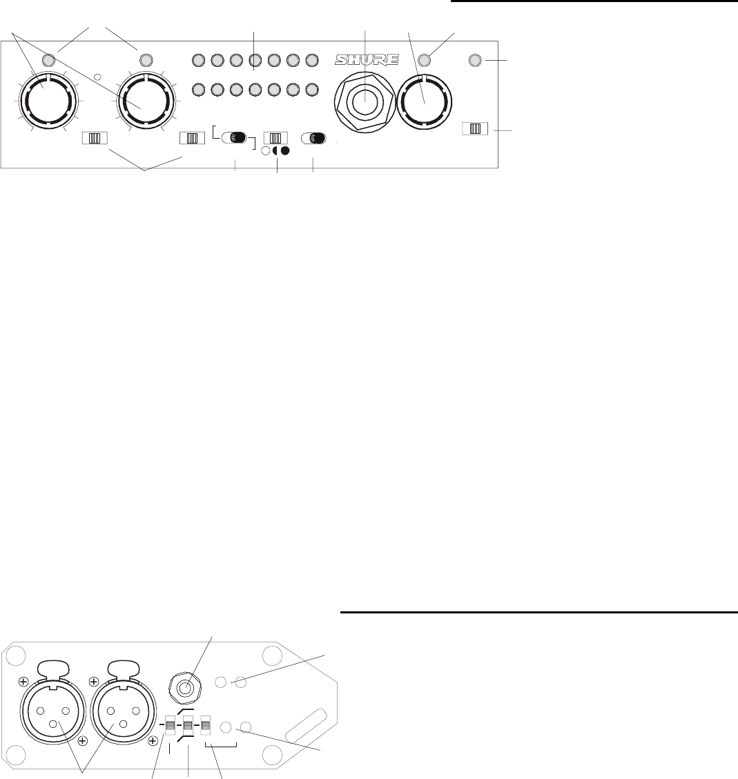
Figure 1. Front Panel
1. Input Gain Controls
Sealed, conductive plastic rotary potentiometers.
2. Input Peak/Limiter LEDs
Dual-color LED illuminates red at 3 dB below clipping; illumi-
nates amber to indicate limiter activity.
3. L-C-R Switches (Input Assignment)
Three-position switch assigns inputs to Left, Center (both
left and right) or Right outputs.
4. Slate Microphone
Condenser microphone with AGC activated by momentary
Slate Microphone Switches. Slate Microphone output ap-
pears at all outputs.
5. Tone Oscillator/Slate Microphone Switch
Toggle switch activates 1 kHz tone oscillator when switched
to the left position and activates the slate microphone when
momentarily moved to the right position. Microphone inputs
are muted when Tone Oscillator or Slate Microphone are
activated.
6. Output Meters
Indicates peak output level in dBu.
7. Meter Brightness Control
Three-position switch adjusts the intensity of illumination of
the output meter; low illumination, normal illumination, or
super-bright illumination.
8. Tape Return Switch
Toggle switch allows external audio to be monitored in the
headphones. The center position is FP24 program audio.
The left and right positions monitor tape return audio; the left
position is locking, and the right position is momentary.
9. Headphone Connector
For stereo and mono headphones with ¼” connectors.
10. Headphone Volume Control
11. Headphone Peak LED
Illuminates 3 dB before clipping of either channel of the
headphone circuit and either channel of Tape Return audio.
12. Power Switch
Three-position switch selects the power source. The unit is
powered from internal batteries when in the left position;
powered from external DC source when in the right position.
Center position is off.
13. Power LED
Two-color LED illuminates green when the unit is powered
and changes to red when batteries require changing. For
external DC, the power LED is always green.
Input Panel Connectors and Controls
MIC INPUTS
12
15V
48V
80
160
LIMITER
LR
LR
TAPE OUT
PHANTOM
LINK
ON THRESHOLD
TAPE RTN
LEVEL
123
4
5
6
7
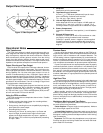
Figure 2. Side Input Panel
1.
Mic Inputs
Transformer-balanced XLR inputs accept microphone level
signals. Pin 2 = hot, Pin 3 = cold, Pin 1 = ground.
NOTE: You can use Shure A15LA line adapters to con-
nect balanced, line-level sources to these inputs.
2. Phantom Power
Three-position switch selects either 48-Volt or 15-Volt phan-
tom power for both inputs. Center position turns phantom
power off.
3. High Pass Filter Switch
Three-position switch selects 80 Hz or 160 Hz corner fre-
quency filters, 6 dB per octave. Filters affect both inputs.
Center position of switch removes filters from the signal
path.
4. Tape Output
3.5 mm (
1
/
8
in.) TRS stereo output (unbalanced) can be
used to feed consumer level DAT, MiniDisc, and CD record-
ers. Tip = Left, Ring = Right, Sleeve = Ground.
5. Tape Return Level Control
Recessed potentiometers adjust Tape Return level feeding
the Headphone Monitor.
6. Limiter Switch
Activates input peak limiter. ON position functions as a dual
mono limiter, with each input signal controlling its own limit-
er. LINK functions as a stereo limiter, with both left and right
inputs controlled simultaneously. Center position of switch
turns limiters off.
7. Limiter Threshold Level Control
Recessed potentiometers adjust peak level of limiter activa-
tion. Can be independently controlled for each input.


