


7
Working Range (Line of Sight)
60 m (200 ft)
Note: Actual range depends on RF signal absorption, reflection
and interference.
RF Carrier Range
X8: 902–928 MHz
X8A: 915–928 MHz
X8B: 902–907.5 MHz, 915–928 MHz
Note: varies by region
Audio Frequency Response
20–20000 Hz
Note: Dependent on microphone type
Total Harmonic Distortion (Ref. 1 kHz, 6 dB below
input clip)
<0.02%, A-weighted, typical
Dynamic Range
>108 dB, A-weighted
Operating Temperature Range
-18°C (0°F)– +50°C (122°F)
Note: Battery characteristics may limit this range.
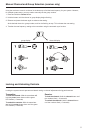
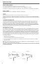
Transmitter Audio Polarity
Positive pressure on microphone diaphragm (or
positive voltage applied to tip of WA302 phone plug)
produces positive voltage on pin 2 (with respect to
pin 3 of low-impedance output) and the tip of the high
impedance 1/4-inch output.
PGXD1 Bodypack Transmitter
Audio Input Level
+10 dBV maximum, at minimum gain setting
-16 dBV maximum, at maximum gain setting
Gain Adjustment Range
26 dB
Input Impedance
1 MΩ
RF Output Power
10 mW
varies by region
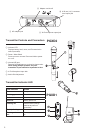
Pin Assignments
TA4M:
1: ground (cable shield)
2: + 5 V Bias
3: audio
4: Tied through active load to ground (On instrument
adapter cable, pin 4 floats)
Dimensions
108 mm x 64 mm x 19 mm (H x W x D)
Weight
128 g (4.5 oz.)(without batteries)
Housing
Molded polycarbonate case
Power Requirements
2 “AA” size alkaline or rechargeable batteries
Battery Life
up to 10 hours
PGXD2 Handheld Transmitter
Audio Input Level
+5 dBV maximum at -10 dB gain position
–5 dBV maximum at 0 dB gain position
Gain Adjustment Range
10 dB
RF Output Power
10 mW
varies by region
Dimensions
254 mm X 51 mm dia. (10 X 2 in.)
Weight
349 g (12.3 oz.) (without batteries)
Housing
Molded PC/ABS handle and battery cup
Power Requirements
2 “AA” size alkaline or rechargeable batteries
Battery Life
up to 9 hours
PGXD4 Wireless Receiver
Dimensions
40 mm X 181 mm X 104 mm (H x W x D)
Weight
289 g (10.2 oz.)
Housing
ABS
Sensitivity
-102 dBm @ 10
-5
BER
Power Requirements
12–18 V DC @ 150 mA, supplied by external
power supply (tip positive)
Audio LED
Red: 2 dB below clip
Amber: 12 dB below clip
Green: 50 dB below clip
Audio Output
Configuration
Impedance balanced
Audio Output Level (1 kHz tone)
XLR connector: –2.5 dBV (into 3 kΩ load)
6.35 mm (1/4”) connector: +10 dBV (into 10 kΩ
load)
Impedance
XLR: 50 Ω
6.35 mm (1/4”): 50 Ω
Pin Assignments
XLR: 1=ground, 2=hot, 3=cold
6.35 mm (1/4”) TRS: Tip=audio, Ring=no au-
dio, Sleeve=ground
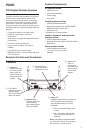
SPECIFICATIONS