8
INTERNAL MODIFICATIONS
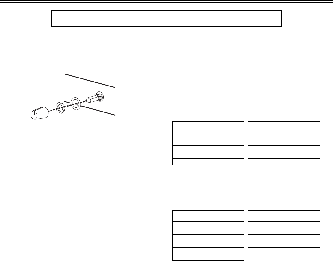
DISASSEMBLY
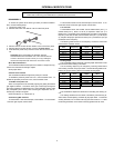
To access the printed circuit board (pc board) for internal modifica-
tions, use the following steps:
1. Unplug the power cord.
2. Remove the knobs and retainer nuts from the front panel.
3. Remove the two screws at each bottom corner of the front panel.
4.
Remove the four screws at each corner of the
back panel.
5. Slide the back panel and pc board out from the rear of the chas-
sis.
CAUTION: When reassembling the SCM262, DO NOT
OVERTIGHTEN the knob retainer nuts. Use a minimal amount
of force to secure the nut (0.6-0.8 Nm (5-7 inlb)). Damage to
the internal components will result if too much force is used.
Mono Mixer Modification
This modification allows all the inputs to be mixed to a single mono sig-
nal sent over both the left and right outputs.
Short jumper X203.
Phantom Power Disable
This modification disables the phantom power per channel.
To disable the phantom power from mic 1, remove resistor R121. To
disable the phantom power from mic 2, remove resistor R122.
15 dB Mic Preamplifier Pad
When a microphone has an extremely high signal, getting the desired
gain might be difficult -- a small turn of the gain control might change the
sound from a whisper to deafeningly loud. This modification adds a 15 dB
Mic preamplifier pad to allow more accurate gain adjustment with ex-
tremely high microphone signals.
Remove R160 (mic 1) or R183 (mic 2).
Hard Panning MIC Channels
To remove MIC 1 from the left outputs, remove R912. To remove MIC
1 from the right outputs, remove R913.
To remove MIC 2/LINE 2 from the left outputs, remove R910. To re-
move MIC 2/LINE 2 from the right outputs, remove R911.
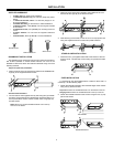
Low-Cut Filter
To eliminate the 80 Hz, low-cut filter, remove resistor R501 (mic 1), or
resistor R519 (mic 2). Place a 10 to 33
F capacitor in X501 (mic 1) or
R502 (mic 2). The polarity of the capacitor does not matter.To change the
frequency of the low cut filter, remove resistor R501 (mic 1) or R519 (mic
2), and place the proper capacitor into X501 (mic 1) or X502 (mic 2) to get
the desired corner frequency.
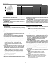
The following tables list the low-cut frequency corners for some of the
most common capacitor values:
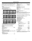
Ducking Depth
This modification adjusts the level of ducking depth attenuation of the
input channels when ducking is activated.
The aux ducking depth may be changed by removing resistor R213
and inserting a resistor into jumper X202. Use the following tables to de-
termine the proper resistor value for the desired ducking depth.
Ducking Threshold
This modification adjusts the threshold for activating the ducking cir-
cuit.
The ducking threshold can be raised or lowered by first removing re-
sistor R333, and then placing a resistor (R) at jumper X303. To lower the
ducking threshold, use a resistor value (R) less than 2k ohms. To raise
the ducking threshold, use a resistor value (R) greater then 2k ohms.
WARNING! Voltages in this equipment are hazardous to life. No user-serviceable parts
inside. Refer all servicing and modifications to qualified service personnel.
Capacitor
Value
Corner
Frequency
Capacitor
Value
Corner
Frequency
.033 F 803 Hz .33 F80 Hz
.047 F 564 Hz .47 F56 Hz
.068 F 390 Hz .68 F39 Hz
.1 F 265 Hz 1.0 F26.5 Hz
.22 F 120 Hz 2.2 F12 Hz
Ducking
Depth
Resistor
Value
Ducking
Depth
Resistor
Value
6 dB 4,000 36 dB 20,000
9 dB 5,000 42 dB 25,000
15 dB 7,500 47 dB 30,000
20 dB 10,000 50 dB 33,000
24 dB 12,000 55 dB 40,000
29 dB 15,000


