


11
ENGLISH
INTERNAL MODIFICATIONS
DISASSEMBLY
To access the printed circuit board (pc board) for internal modifica-
tions, use the following steps:
1.
Unplug the power cord.
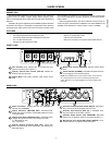
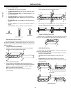
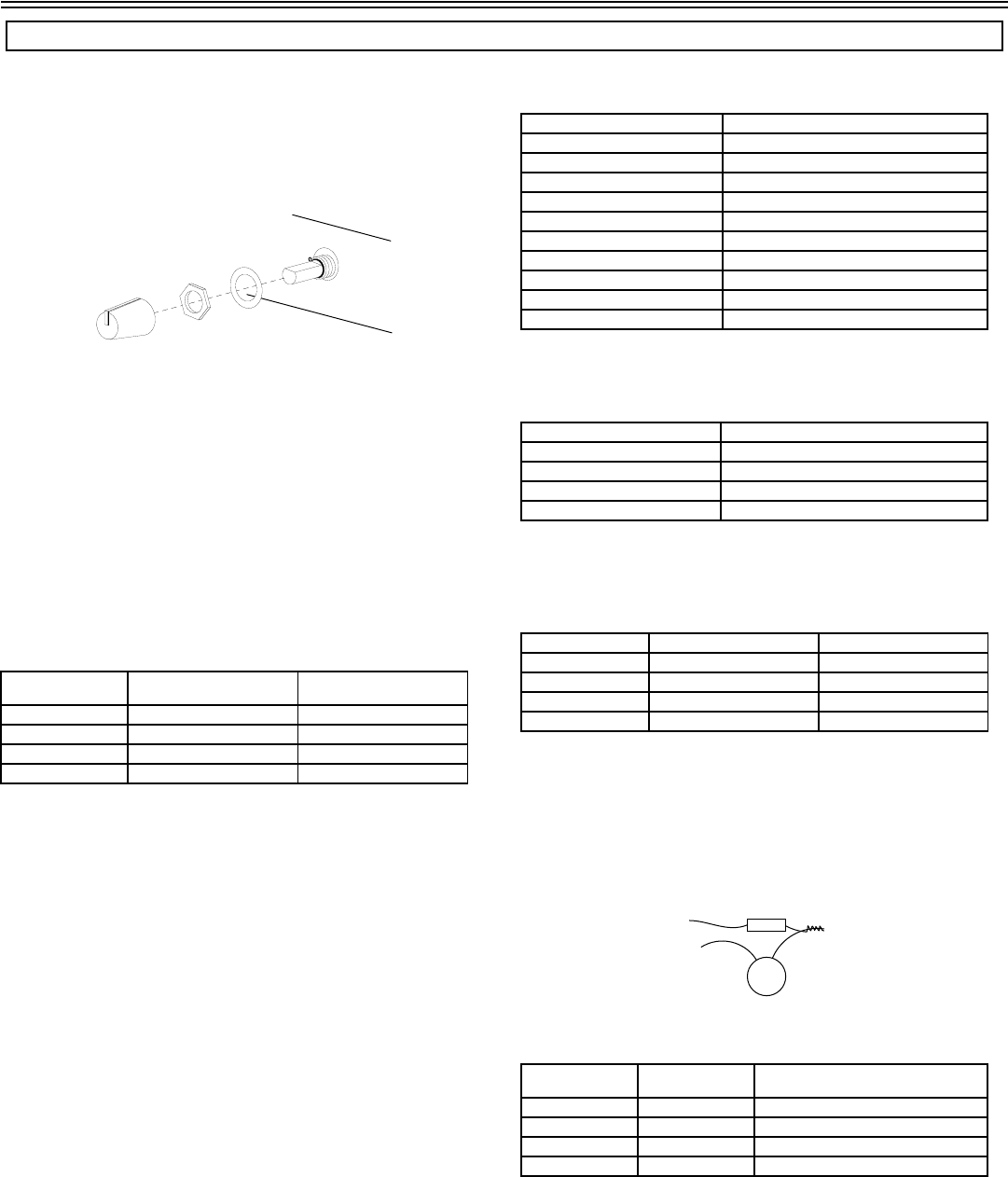
2. Remove the knobs and retainer nuts from the front panel (See
Figure 2).
KNOB ASSEMBLY
FIGURE 2
3.
Remove the four screws at each corner of the
back panel.
4. Remove the two screws at each bottom corner of the front panel
5. Slide the back panel and pc board out from the rear of the chas-
sis.
CAUTION: When reassembling the SCM268, DO NOT
OVERTIGHTEN the knob retainer nuts. Use a minimal amount of
force to secure the nut (0.6-0.8 N⋅m (5-7 in⋅lb)). Damage to the
internal components will result if too much force is used.
LOW-CUT FILTER
To bypass the built-in low-cut filter for a given channel, remove the
specified resistor and place a 10
μ
F to 33
μ
F capacitor in the specified pc
board location (polarity does not matter). Refer to the following table:
To select a particular corner frequency for the low cut filter, remove the
R18, R28, R38, or R48 resistor for a given channel as specified above.
Then, in the corresponding pc board location (X17, X27, X37, or X47),
place a capacitor of the specified value (polarity does not matter). Refer
to the following formula for selecting the correct capacitor value for the de-
sired corner frequency.
where:
C = value of capacitor in μF
F = corner frequency (-3 bB) for low-cut filter in Hz
The following table lists the low-cut frequency corners for some of the
most common capacitor values:
PHANTOM POWER DISABLE
To disable phantom power for a given microphone input, remove the
specified resistor as listed in the following table:
LINE PAD
To insert a 50 dB line pad for a given microphone input, remove the
specified resistor and short the solder points at the specified pc board lo-
cations. Refer to the following table:
HOT MIC PAD
Some condenser mics have a high output. In order to avoid overdriv-
ing the input stage, the user may need to set the input pot lower than de-
sired. To fix this problem, the user can place an 11 dB pad into the input
gain stage of a selected channel.
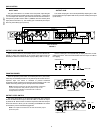
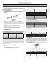
1.
Twist together the leads from one side of a 15 k
Ω resistor and a
0.1 μF capacitor:
2. Solder the free ends of the resistor-capacitor combination into the
holes at the jumper position indicated by the following table and
remove the corresponding surface mount resistor.
WARNING! Voltages in this equipment are hazardous to life. No user-serviceable parts inside. Refer all servicing to qualified service personnel.
Channel Remove Resistor from: Place 10μF to 33μF
Capacitor in:
1R18 X17
2R28 X27
3R38 X37
4R48 X47
C 26.5 F⁄=
Capacitor Value (μF) Low-Cut Frequency Corner (Hz)
.033 803
.047 564
.068 390
.1 265
.22 120
.33 80
.47 56
.68 39
1.0 26.5
2.2 12
Channel Remove Resistor:
1R15
2R25
3R35
4R45
Channel Remove Resistors: Short Solder Points:
1 R12, R13, R15 X11 and X14
2 R22, R23, R25 X21 and X24
3 R32, R33, R35 X31 and X34
4 R42, R43, R45 X41 and X44
Channel Remove
Resistor
Insert Resistor-Capacitor
Combination at Jumper
1R18 X17
2R28 X27
3R38 X37
4R48 X47
15 KΩ
0.1 ΜF