


8
ENGLISH
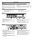
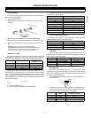
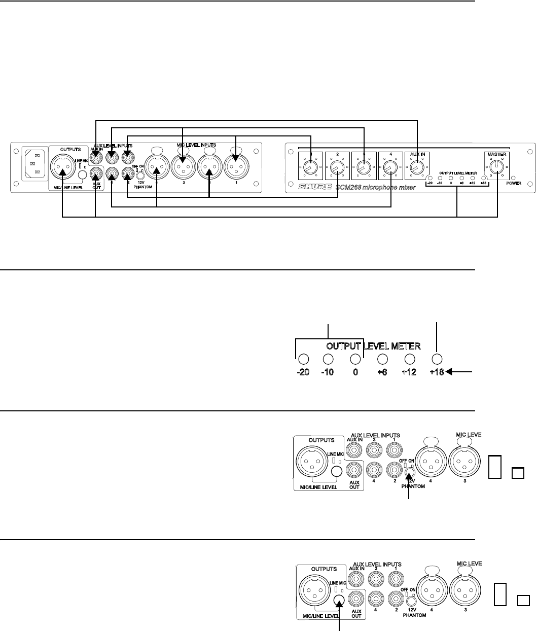
GAIN CONTROL
INPUT GAIN
The gain control knobs 1-4, located on the front panel, adjust the gain
for both microphone and auxiliary-level inputs of channels 1-4 (see Figure
1). For example, the channel 1 gain control is used for both the channel 1
microphone input (MIC LEVEL INPUT 1)
and
the channel 1 auxiliary level
input (AUX LEVEL INPUT 1). The auxiliary gain control knob (AUX IN) af-
fects only the auxiliary input (AUX IN).
OUTPUT GAIN
The master output gain control knob (MASTER) adjusts gain to both
the XLR balanced output (MIC/LINE LEVEL) and the auxiliary level output
(AUX LEVEL).
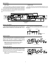
OUTPUT LEVEL METER
The six LEDs on the front panel labeled OUTPUT LEVEL METER illu-
minate to reflect the peak level of the mixed output signal from the
SCM268 (in reference to balanced line output) in dBu (0 dBu = 0.775 V).
Use the master gain control (MASTER) to adjust peak levels, as indi-
cated by the LEDs. The red LED illuminates when the output is 2 dB be-
low clipping.
PHANTOM POWER
When the phantom power switch on the back panel is on (12V PHAN-
TOM-ON), the SCM268 provides 12 V of phantom power to each XLR mi-
crophone input. The switch is recessed to prevent accidental
engagement. Most condenser microphones require phantom power. Use
it when connecting these types of microphones to the SCM268.
NOTE: Phantom power does not affect the operation of balanced
dynamic microphones. With phantom power on, they can be
connected to the SCM268 in combination with condenser
microphones that do use it.
OUTPUT LEVEL SWITCH
The output level switch on the back panel (MIC/LINE OUT) sets the
level of the balanced XLR output. When set to MIC, it reduces the output
by about 50 dB. Set the switch so that the output level matches the input
level of the device to which you are connecting the SCM268. The switch
is recessed to prevent accidental engagement.
NOTE: The output level switch does not affect the auxiliary output
(AUX OUT) level.
Channel 1
Channel 3
Channel 2
Channel 4
Master Output
Auxiliary Channel
GAIN CONTROL
FIGURE 1
GREEN-Nominal
RED-Clip
Peak in dBu
Phantom Power Switch
OFF ON
Output Level Switch
LINE MIC