


14
INTERNAL MODIFICATIONS
WARNING: All modifications must be performed by qualified service
technicians.
NOTE: Remove AC power before opening the unit.
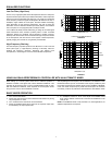
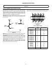
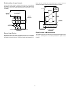
This section describes SCM810 modifications that can be made using
solder “jumpers” on the printed circuit board; the pads where jumpers may
be used are placed close together so that a single solder drop functions as
a jumper. Note too that:
1. The only printed circuit board legends used for these modifications
are jumpers (X's) and resistors (R's).
2. Where resistors are to be added, through-holes are present on the
board.
3. For individual channel modifications, the first number of the reference
designation refers to its channel number, i.e., R1027 refers to a
Channel 1 resistor, X7216 refers to a Channel 7 jumper, etc. All
references to Channels 1 through 8 in the following paragraphs use
Channel 1 jumpers and resistors as reference. Modifications affecting
the Master section are preceded by the number “9" (X901, etc.).
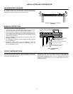
To gain access to the main printed circuit board, remove the 8 Phillips head
screws securing the top cover, and remove the top cover. Most
modifications can be made from the top of the main board.
Line-Level Output to Mic-Level Output
Procedure:
Short jumper X901. Remove resistors R900 and R909.
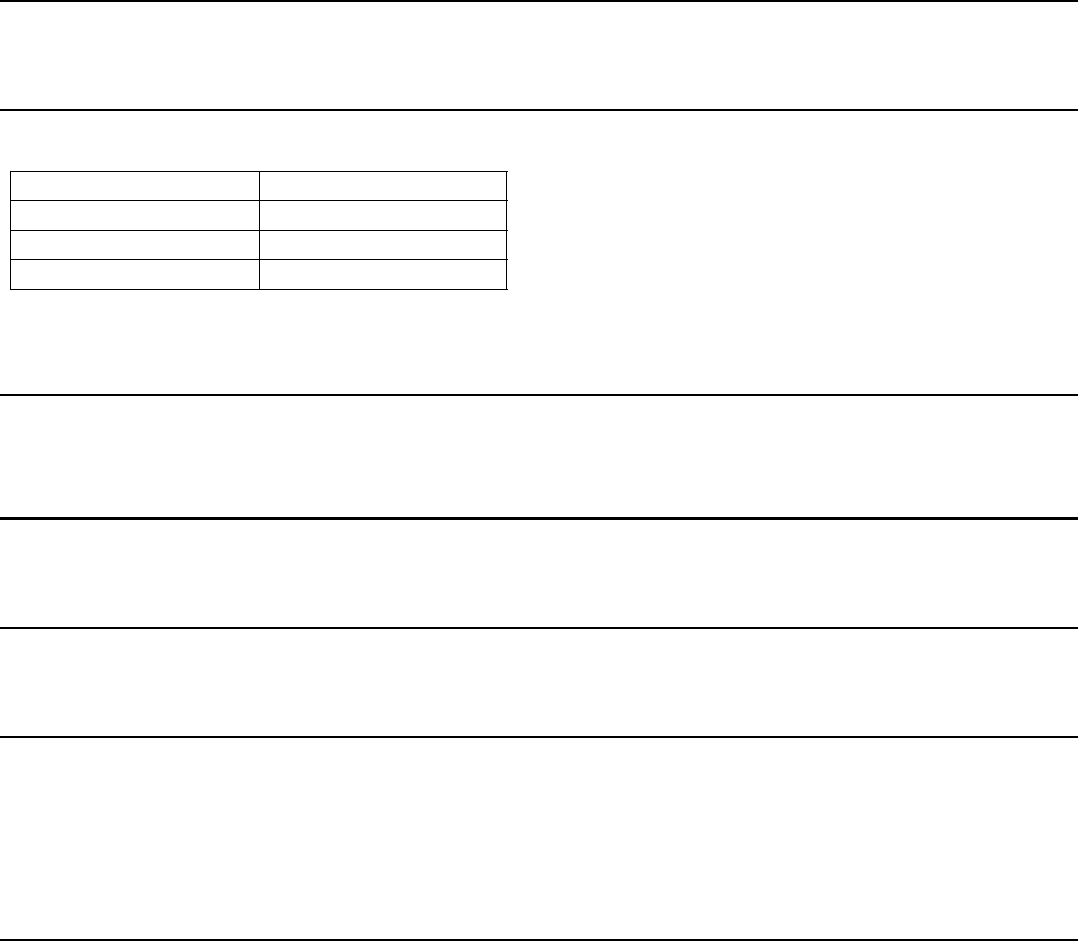
Disable Master Level Control
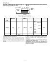
The Master gain control can be disabled so it cannot be tampered with. The
table indicates the resistor value to be used for the desired gain.
Procedure:
Remove resistor R9230. Install new resistor at jumper X914.
Change Limiter Threshold
All three threshold settings (+16, +8 and +4 dBm) can be changed. To shift
the threshold down by 6 dB, resistor R will be 82 k. To shift the limiter
thresholds up by 6 dB, R will be 330 k.
Procedure:
Remove resistors R9177 and R9180. Install new resistor R at jumper X907.
Local Aux Operation
With linked mixers, the Aux input from a modified mixer does not link.
Procedure:
Remove resistor R9024.
Direct Out to Post-Fader
A channel's Direct Out phone jacks can be changed from pre- to post-fader. Procedure:
Short jumper X106. Remove resistor R1011.
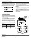
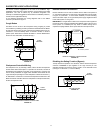
Direct Out to Post-Fader Send/Return (Insert)
Changes a channel's 1/4-inch Direct Out jack to a post-fader insert point.
Send is tip of phone jack; return is ring. Insert jacks are useful for inserting
line-level signal processors into a channel. For instance, a parametric EQ
or compressor/limiter can be inserted into a channel for additional
processing.
Procedure:
Short jumpers X101, X102, X105 and X106. Remove resistors R1011 and
R1020.
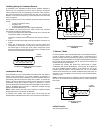
Direct Out to Gated Direct Out
This post-fader, post-EQ channel output is gated, but without NOMA. In this
mode, if the Local/Global switch is in “Local”, a manual mix of channel
inputs is present at the Line output. The Off-Attenuation level of the Gated
Direct Out signal is infinite.
Procedure:
Short jumpers X104 and X906 (in Master section). Remove resistor R1011.
Master Section Gain Resistance
-6 dB 5.1 k
0 10 k
6 dB 20 k