


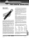

W15HT/58 WIRELESS MICROPHONE
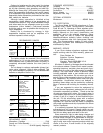
FIGURE 1
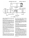
GRILLE:
Protects the SM58 acoustic transducer of the
W15HT/58, and helps minimize the effects of breath
sounds and wind noise.
MICROPHONE LEVEL Rotary Control: Used in con-
junction with the wireless microphone receiver, this
control provides audio level adjustments for various
sound sources. A small screwdriver is supplied to make
adjustments. (NOTE: The supplied screwdriver has a
plastic blade; use of a metal-blade screwdriver may
damage the rotary control.) A rubber plug is provided to
cover the adjustment hole if desired.
MICROPHONE ON/OFF Slide Switch: Permits the
user to “mute” the microphone without turning the
transmitter off. This avoids the “pop” that may accom-
pany power turn-on and turn-off, and generally prevents
pickup of unwanted signals by an “open” receiver.
POWER ON/OFF Slide Switch: Applies power to the
transmitter circuitry. Like the Microphone On/Off
switch, it is a low-profile type and is oriented perpen-
dicular to the Microphone On/Off switch to further pre-
vent accidental turn-off.
UPPER CASE: In addition to the controls, this section
contains the transmitter circuitry.
LOCKPLATE: Used to lock the controls against
accidental movement. Installed by removing the upper
case screw just above the control area, inserting the
lockplate, and replacing the screw.
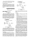
SETUP
With the transmitter POWER ON/OFF Switch in the
OFF position, remove the end cap (push in, twist
counterclockwise, and pull). Insert a new 9-volt alkaline
or lithium battery in the compartment (carbon-zinc bat-
teries will work, but they provide a diminished operating
life of about 2.5 hours). Observe the proper
polarity: the large (negative) terminal in the large
channel and the small (positive) terminal in the small
channel (see battery compartment label).
Operation with a fully charged, heavy-duty, 8.4-volt
nickel-cadmium rechargeable battery is also permissi-
ble and will provide approximately 3 hours of operation.
IMPORTANT: Do not use a “conventional” 9-volt-sized
nickel-cadmium battery; its 7.2-volt output will not
operate the transmitter properly.
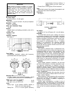
BATTERY CHECK
Turn the POWER Switch on and observe the Battery
Test LED. The LED should light momentarily, indicating
adequate voltage. If it remains lit (clearly visible in nor-
mal room light), the battery voltage has dropped below
7.0 volts and should be replaced (alkaline or lithium) or
recharged (nicad). If it does not light at all, the battery
should be discarded.
SETTING AUDIO LEVEL
Place the POWER Switch of the receiver in the ON
position. The green POWER LED will light.
Move the microphone POWER ON/OFF Switch to the
On position. Observe the receiver RF SIGNAL LEVEL In-
dicator. In the Shure W20R receiver, the yellow signal
LED should be continually lit, indicating adequate RF
signal strength for good transmission. If the LED con-
tinually flickers or does not light, consult the
Troubleshooting section of the receiver manual.
In the Shure W25DR receiver, one of the green LED
segments should light, indicating adequate RF signal
strength for good transmission. A yellow LED indication
means less than optimum signal transmission and/or
reception, and a red LED indicates less than satis-
factory operation.
2