


27
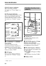
7 RF (radio frequency) indicator
The color indicates the strength of the
RF input signal.
On in green: RF input is 25 dBµ*
or more.
Off: RF input is less than 25 dBµ*.
8 SET button
Press to change display parameters.
For details, see “Settings” on page
37.
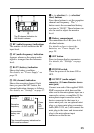
9 TUNER OUTPUT (audio
output) connector (XLR type)
Connect to the audio input connector
of a mixer or amplifier, etc.
0 LEVEL (audio output level)
switch
Sets the output level of the TUNER
OUTPUT connector to –28 dBm
or –58 dBm.
Select the setting according to the
input level of the equipment connected
to the tuner.
qa TRS PHONE (tuner audio
output) connector (1/4-inch jack)
Connect to the audio input connector
of a mixer or amplifier, etc. The
output level from this connector is –30
dBm.
qs DC IN 9V (DC power input)
connector
Connect the supplied AC adapter here.
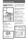
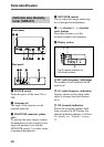
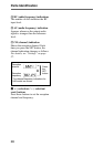
Diversity tuner module
(URX-M1)
1 SET button
Press to change display parameters.
For details, see “Settings” on page
37.
2 RF (radio frequency) indicator
The color indicates the strength of the
RF input signal.
On in green: RF input is 25 dBµ*
or more.
Off: RF input is less than 25 dBµ*.
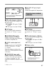
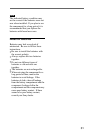
3 Display section
Reception
channel
Reception
frequency
Press
the
SET
button.
The channel/frequency indications for
U66 model are shown.
AF
RF
CH
A
B
C
The C channel indication for
U66 model is shown.
......................................................................................................................................................................
* 0 dBµ = 1 µVEMF