


7
US
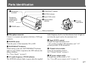
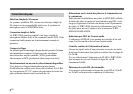
3 POWER/BATT indicator
4 AF/PEAK indicator
5 Input LEVEL control
6 Channel select
switches
7 RF power
output switch
1 Microphone
connector
2 POWER switch
Battery compartment
Microphone
release button
(under side of
the unit)
Parts Identification
1 Microphone connector
Connect to a dynamic microphone which has a XLR type
connector.
2 POWER switch
Turns the power of the transmitter ON or OFF.
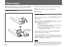
3 POWER/BATT indicator
When turning on the unit, the POWER/BATT indicator
lights in green. While in operation, the LED indicates the
battery condition.
See “Power Supply” on page 8.
4 AF (audio frequency) /PEAK indicator
The AF/PEAK indicator lights in green when the supplied
audio frequency level is over the reference level. It lights in
red when the signal reaches the maximum level.
5 Input LEVEL control
Controls the input attenuation level.
“–60” position provides 0 dB attenuation, and “–10”
position provides 50 dB attenuation.
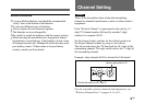
6 Channel select switches
Select the transmitting channel.
See “Channel Setting” on page 9.
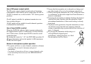
7 RF power output switch
In normal use, set the switch to “50”.
See “Use of RF power output switch” on page 11.