


26 GB2 User Guide
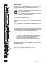
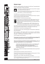
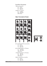
Stereo Input
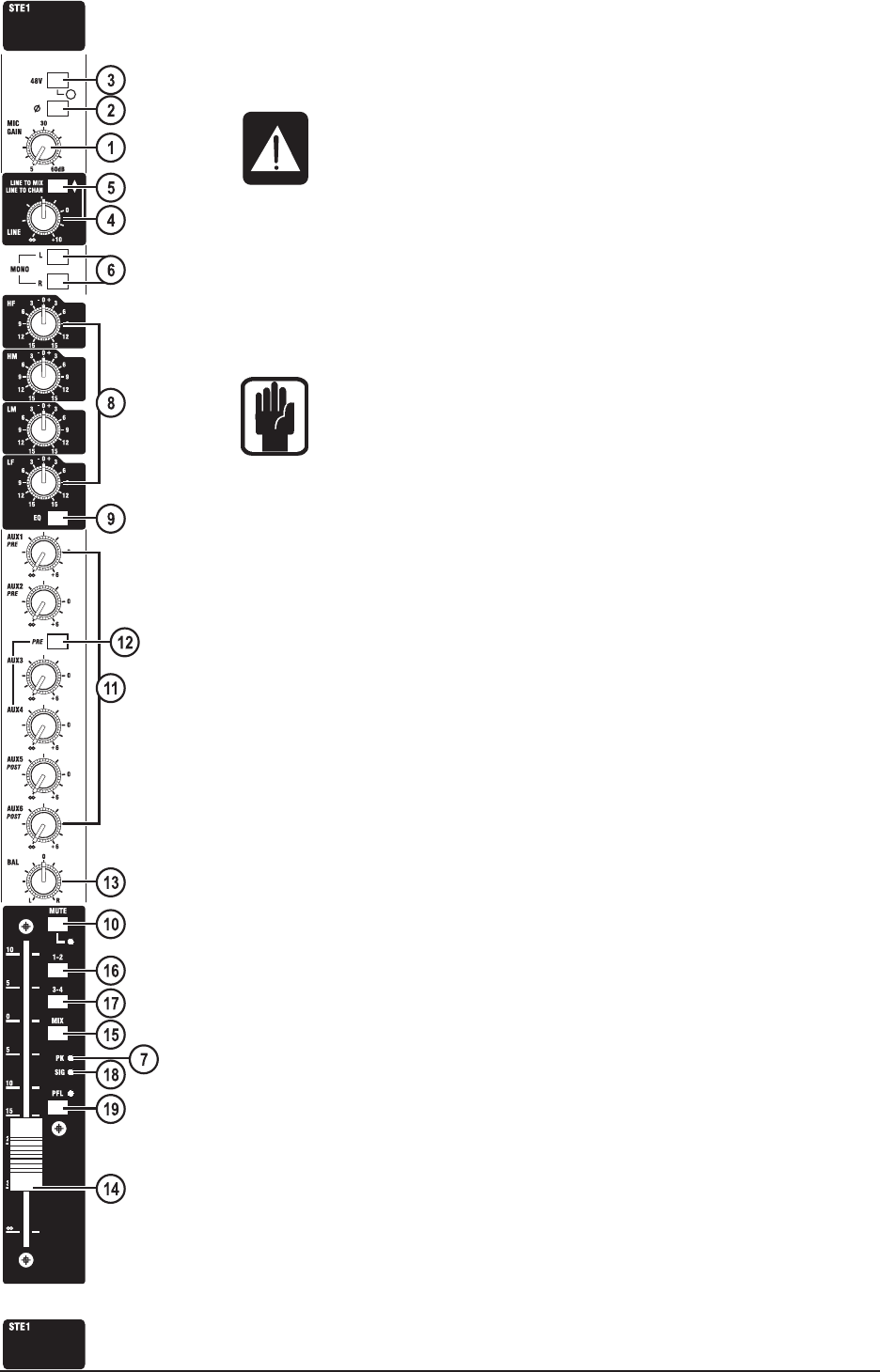
MIC GAIN (1) adjusts the sensitivity of the stereo pair of mix XLR inputs. They are electronically
balanced, and are located on the rear connector panel.
The 48V switch (2) applies 48V phantom power to the input XLRs. An adjacent
LED indicates when the phantom power is on.
Don’t connect microphones with the phantom power switched on. Only switch the
phantom power on or off with the output fader down.
The PHASE switch (3) inverts the phase of the left channel XLR.
The LINE level control (4) adjusts the signal level from the stereo pair of line input 1/4” jacks on
the rear connector panel. The line inputs are balanced.
The LINE TO MIX/LINE TO CHAN (5) switch works as follows:
When the switch is in the raised position (LINE TO MIX) the signals from the line
inputs are routed (via the line level control) directly to the main mix l & r busses.
The XLR mic inputs are routed through the channel. This, in effect, gives an extra
stereo return input.
When the switch is in the depressed position (LINE TO CHAN) the signals from
the line inputs are routed through the channel. The mic XLR inputs are not used.
The L switch (6) routes the left input signal to both L and R channels in the module. The R switch
similarly routes the right input signal. Pressing L and R together mono sums the input.
The PEAK LED (7), monitors both left and right signals pre-EQ.
The EQ section (8) has four bands, with shelving high and low frequencies and peaking high-
mid and low-mid bands.
The HF control gives +/-15dB cut/boost at 12KHz. The LF control gives +/-15dB cut/boost at
60Hz. The HM control gives +/-15dB cut/boost at a centre frequency of 2.5kHz, and the LM
control gives +/-15dB cut/boost at a centre frequency of 450Hz.
The EQ is switched in by the EQ switch (9).
The stereo signal in the module is turned on and off by the MUTE switch (10). An adjacent LED
illuminates when the module is muted. The PFL will still work whilst the module is muted. The
Line To Mix routing [see (5) above] is not affected by the MUTE switch.
A mono sum of the signal is sent to the AUX 1-6 busses via individual level pots (11). Aux 1 and
2 are both post-eq* pre-fade feeds. Aux 3 and 4 are jointly selectable, via the PRE switch (12) to
be pre-fade* or post-fade feeds. Aux 5 and 6 are post-fade feeds*.
* Note: there is a dealer-implemented option to connect aux 1 and 2 feeds as pre-eq
pre fade. This would also affect aux 3 and 4 when they are selected as pre-fade.
Aux 5 and 6 may be connected to follow aux3/aux4 pre/post routing.
The warranty is voided if these options are implemented by anyone other than an
Authorised Soundcraft Dealer.
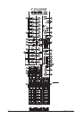
The BAL control (13) allows the stereo image to be balanced between the left and right channels
within the module.
Post-fader signal level is controlled by a 100mm stereo fader (14).
The signal can be sent to the stereo mix busses (15), groups 1-2 (16) and groups 3-4 (17). Note
the use of group 1 & 2, and group 3 & 4 as 2 sets of stereo pairs.
A signal LED (18), next to the fader, meters the post-EQ, pre-mute signal.
The PFL switch (19) feeds a mono sum of the pre-mute signal to the monitor output and phones
output. An adjacent LED indicates when the PFL is on.