


29GB2 User Guide
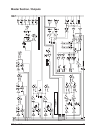
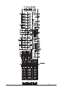
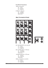
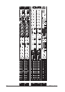
Master Section
GROUPS
There are four Groups. They are arranged as two stereo pairs.
Each GRP fader (1) is placed after its Group insert point (on the rear panel). The fader controls
the signal level which is then fed to the Group Output XLR on the rear connector panel.
Each PFL button (2) feeds its group’s post-insert pre-fader signal to the monitor outputs and
phones output.
Each post-fader group signal pair can be routed to the main mix stereo pair via the MIX switch
(3). Each pair of groups, 1-2 and 3-4, has a WIDTH pot (4); it is used to adjust the group pair’s
signal within the stereo image of the main mix. The separation of the two group signals in the
pair is maintained when the width pot is set to stereo, e.g. group 1 signal is routed to the main
mix left bus, and group 2 is routed to the main mix right bus; when the width pot is fully at mono,
a sum of group1 and group 2 is routed to the main mix left and main mix right busses.
Each group’s post-fader signal may be routed to one or both of the 2 matrix busses via the
matrix input pots (5).
AUX MASTERS
Each AUX master level pot (6) controls the level fed from its own aux bus to its aux output.
Aux outputs 1-4 are balanced via XLR connectors, aux 5 and 6 outputs are balanced via 3-pole
1/4” jack sockets on the rear connector panel.
Each AFL button (7) feeds its aux post-fader signal to the monitor output and phones output.
MATRIX MASTERS
Each MTX MASTER level pot (8) controls the level fed from its own matrix bus to its matrix
output on the rear connector panel.
Each AFL button (9) feeds its matrix master post-fader signal to the monitor output and phones
output.
Each MUTE switch (10) will mute its own matrix output signal.
Mix L, R and Mono Outputs
Each of the 2 main mix busses, Left and Right, has its own insert point. These are located on the
rear connector panel. The main mix busses share a stereo Fader (11) which follows the insert
points in the signal paths.
The post-fader signal for each bus is then routed to the following places:
• its main output XLR on the rear connector panel,
• feeds to the matrix 1- 2 busses (12),
• the REC output sockets on the rear connector panel,
• the MONITOR SOURCE select switch MIX (13).
A mono sum of the L & R outputs is available on the MONO output XLR on the rear connector
panel.