


MHP3 User Manual ◄ 19
OPERATION
CHECKING SUCTION HOSE
Make sure the suction hose (from the hydraulic tank to
the pump inlet) is not kinked and is clamped securely.
This reduces the risk of pump cavitation and sucking air
into the system. All pump ttings should be tight.
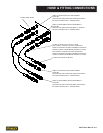
CHECKING HYDRAULIC LINES AND
FITTINGS
Check for loose ttings, leaks, etc., throughout the
hydraulic circuit.
• Check hydraulic lines and ttings for leaks, kinks,
etc. daily. Do not use your hand to perform this
check.
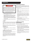
FILLING THE RESERVOIR
Make sure the engine is stopped before opening the ll-
er cap. Fill slowly with the recommended uid. Add uid
as needed. Secure the ller cap before restarting the
engine. Refer to the hydraulic uid page in this section
for determining correct uid level.
• Change the hydraulic lter element every 200 hours
of operation. Change more often if cold, moist or
dusty conditions exist.
• Check oil cooler for debris. Remove debris with air
pressure.
REMOVING CONDENSED MOISTURE
FROM HYDRAULIC FLUID
Condensation is a frequent problem with cool mobile
hydraulic circuits. This condition occurs in moist or cold
climates. When warm air in the hydraulic tank draws
moisture from the cooler air outside, water accumulates
in the tank.
• Check hydraulic uid level daily. Add uid per speci-
cations in this manual (Refer to HYDRAULIC FLU-
ID in this section).
• Remove condensed moisture from the hydraulic
uid by pumping the hydraulic uid into a 5 gal/20l
container through the pressure hose. Make sure the
engine is at idle when performing this procedure.
When the hydraulic reservoir is empty, turn the en-
gine OFF immediately.
• Allow the uid to sit long enough for the wa-
ter to settle to the bottom of the container.
Slowly pour the uid back into the hydrau-
lic tank, avoiding the water at the bottom of the
container.
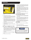
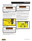
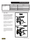
• The track tension is adjusted with the unit lifted off
the ground. Between the drive wheel and front idler
wheel, there are 3 smaller rollers.
• Once the unit is lifted off the ground, adjust the track
tension to achieve 3/8” to ½” sag below the center
small roller.
ADJUSTING TRACK TENSION