


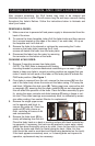

5. Examine the center channel of the fader body (found inside the bottom of
the fader casing) and if dirty, clean using cotton buds.
6. Re-assemble and lubricate the fader as follows:
a) Secure the end block and guide rail onto the fader body.
b) Insert track into the fader body.
c) Insert slider assembly onto guide rail and into the fader body. Move
slider from end to end to disperse the oil evenly. Carefully wipe away any
excess oil using a tissue or cloth.
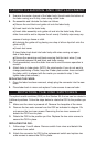
d) Lubricate the guide rail by placing one drop of silicon liquid oil onto the
guide rail
(F).
e) Insert dust cover.
f) Insert fader track back into fader body with wires coming out open
end of fader body.
g) Secure the remaining end block ensuring that the track wires (I) are
not pinched between the end block and fader casing.
7. Once assembled, move the slider from end to end to ensure operation is
smooth.
8. Attach fader to fader plate. (NOTE: As noted earlier if you do not want to
change positioning of fader, keep the 2 fader plate screws loose and shift
the fader until it is aligned with the marks you created in step 1, then
tighten fader plate screws.)
REPLACING THE FADER:
1. Once the fader has been removed, simply plug the connector into the new
fader.
2. Place fader back in mixer and replace 2 outer screws to secure fader.
FADER CLEANING AND REPLACEMENT
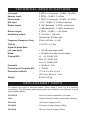
ROTATING THE OS2 SWITCHES
The optical scratch switches (OS2) on the Stanton SA.5 mixer can be rotated to
8 different positions. Follow the steps below to rotate the OS2 to the position you
like:
1. Make sure the mixer is powered off. Remove the faceplate of the mixer.
2. Remove the two outer screws from the OS2 as indicated in diagram. Do
not remove the two inner screws. Removing the two inner screws will
detach the OS2 from its plate.
3. Rotate the OS2 to the position you like. Replace the two outer screws to
secure the OS2 in place.
REPLACING THE OS2:
1.
Follow steps 1 and 2 above. Remove switch from mixer and detach the
connector from switch.
2. Attach the connector for OS2 to the replacement switch and replace two
outer screws to secure the OS2 in place.