


3-3
Safety Information and Technical Specifi cations
DESIGNED IN USA
BAR CODE
TP4 TP3
+
C77
+
C78
+
C84
JP1
1
4
JP3
1
4
JP62
13
JP61
1
3
JP25
1
3
JP46
1
2
5
6
JP47
1 2
5
6
1
JP54
A1
B1
A18
B18
JSM1
A1
B1
A18
B18
JSM2
MH1
MH2
RP14
12
22
23
33
34
44U40
23
34
44
Y1
Y2
R69
OPEN 45 C
1-2 50 C
2-3 55 C
9071 RST
ACT LED TEST
JP62
1-2 WITH FAN
2-3 NO FAN
2-3 NO FAN
1-2 WITH FAN
JP61
JP25: OH TEMP
UPGRADE #2
UPGRADE #1
FA N
SAS IN #4-#7
SAS IN #0-#3
+5V+12V
REV 1.00
BPN-SASI28A
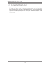
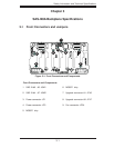
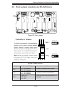
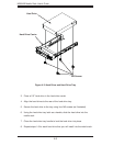
3-3 Front Jumper Locations and Pin Defi nitions
Explanation of Jumpers
To modify the operation of the backplane,
jumpers can be used to choose between
optional settings. Jumpers create shorts
between two pins to change the function of
the connector. Pin 1 is identifi ed with a square
solder pad on the printed circuit board.
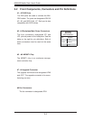
Note: On two-pin jumpers, "Closed" means
the jumper is on and "Open" means the
jumper is off the pins.
Connector
Pins
Jumper
Setting
3 2 1
3 2 1
General Jumper Settings
Jumper Jumper Settings Note
JP61
1-2: Fan enabled
2-3: Fan disabled
Enables or disables the fan power.
JP62
1-2: Fan enabled
2-3: Fan disabled
Enclosure monitor enable/disable.
JP25
Open: 45
o
C
1-2: 50
o
C
2-3: 55
o
C
Allows the overheat temperature to be
adjusted.
JP62
JP61
JP25
Figure 3-2: Front Jumper