


TASCAM IF-AE8HR
TASCAM IF-AE8HR 5
occurs if there is no clock signal or the signal is ±6%
outside the nominal frequency. In these cases, once a
valid clock signal is received again, the indicator will
light steadily.
3 CLOCK switch and indicators
This switch allows you to cycle between the six pos-
sible clock sources for the IF-AE8HR: the
WORD
SYNC – IN
9 connector, the DIGITAL I/O (TDIF-1)
8 connector, or any of the four two-channel AES/
EBU connectors (
DIGITAL I/O (AES/EBU) INPUTS
(1/2, 3/4, 5/6, 7/8)
7), as shown by the indicators to
the right of the switch.
NOTE
There should usually never be more than one word clock
signal in a digital audio system. If there is more than one
word clock, at worst, damage may occur to speakers,
amplifiers, etc. as a result of high-frequency noise gener-
ated by word clock incompatibilities, etc..
4 SAMPLING FREQUENCY switch and
indicators
This switch allows you to select the sampling fre-
quency at which the IF-AE8HR outputs data, either
to the XLR-type connectors, or to the TDIF-1 con-
nector:
44.1k, 48k, 88.2k or 96k.
There are also two other settings that may be selected
with this switch:
DUAL and HI SPEED, which only
become options when one of the high-frequency
options (
96k or 88.2k) has been selected. Repeated
presses of this switch will cycle between the follow-
ing settings:
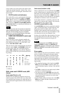
●
= LED off
❍
= LED on
DUAL mode and HI SPEED mode (AES
format)
Usual mode (FS=44.1 or 48)
In this mode, one XLR-type connector carries two
channels of data. Since the IF-AE8 is provided with
four such XLR-type connectors for input and four for
output, the data for eight channels can be transferred
in total.
DUAL mode (Fs=88.2k or 96k)
Data is transferred in over two channels in the DUAL
mode. In high-frequency sampling modes (88.2k and
96k), there is twice the amount of data compared to
the usual modes (44k and 48k). In
DUAL mode, one
XLR-type connector carries the data for one channel,
allowing four channels in total to be transferred.
In this mode, channel 1 is carried by connector
1-2,
channel 2 by connector
3-4, channel 3 by connector
5-6, and channel 4 by connector 7-8.
HI SPEED mode (Fs=88.2k or 96k)
In the HI SPEED mode, data is transferred at double
speed. As mentioned above, in high-frequency sam-
pling modes (88.2k and 96k), there is twice the
amount of data compared to the usual modes (44.1k
and 48k). Here, the transfer speed is doubled, so that
one connector can carry two channels’ data.
In theory, this would allow eight channels to be trans-
ferred at high speed, but for the reason below, only
four channels may be transferred using the IF-
AE8HR.
NOTE
NOTE
In TDIF version 2 format, only the
DUAL
mode is sup-
ported. If
HI SPEED
is selected, only
DIGITAL I/O
(AES/EBU)
connectors 1-2 and 5-6 are used. Therefore,
INPUT
and
OUTPUT
terminals
3-4
and
7-8
cannot be
used in this mode.
Error modes
These LEDs are also used as error indicators, to show
an error condition with regard to the input signals.
The selected frequency indicator will flash to show
an error under the following circumstances. When
appropriate steps are taken to correct the problem, as
shown below, the indicator will stop flashing and will
light steadily.
• The sampling frequency of the signal at the
AES/
EBU
inputs and the TDIF-1 connector differ. Cor-
rect the sampling frequency settings of the attached
units.
• The
TDIF-1 connection is not made properly. Make
sure that it is connected correctly.
• The signals at the four
AES/EBU inputs have dif-
ferent sampling frequencies. Make sure that all sig-
nals received at these connectors are at the same
sampling frequency.
• Incorrect data is being received at one of the
AES/
EBU
inputs. Make sure that all data sources are
correctly set up.
44.1k 48k 88.2k 96k DUAL
HI
SPEED
Meaning
❍●●●●●
44.1 kHz
●❍●●●●
48 kHz
●●❍●❍●
88.2 kHz DUAL
●●●❍❍●
96 kHz DUAL
●●❍●●❍
88.2 kHz HI SPEED
●●●❍●❍
96 kHz HI SPEED