


Section 3 Detailed Component Descriptions
CDR-1000 RECEIVER CONTROLS, CONNECTORS AND INDICATORS
power
R
1
1 2
2
Featuring
RE-1 CDR-1000
R
menu
set
menu
set
4
3
4
3
4
1
2a
2b
2c
2d
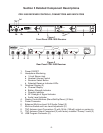
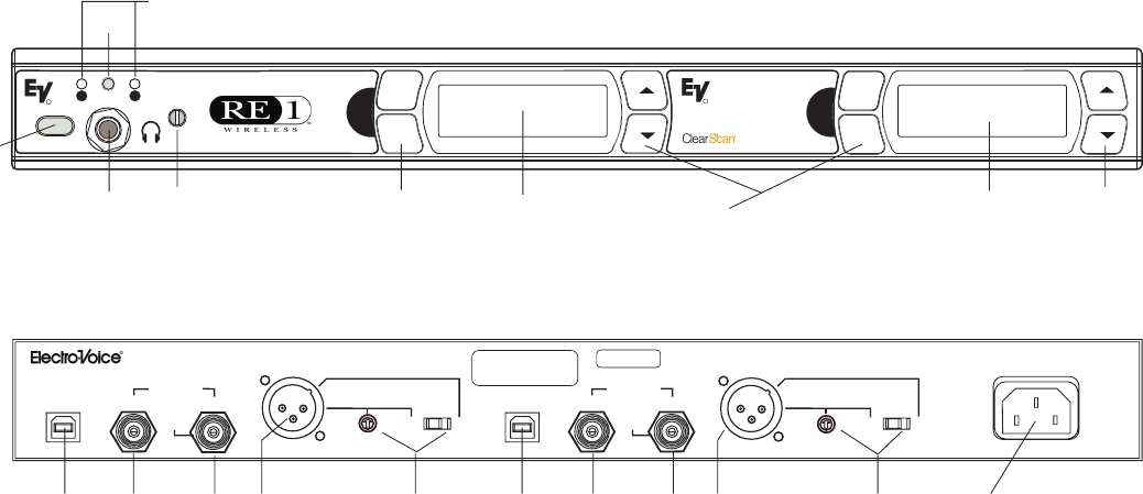
Figure 1
Front Panel CDR-1000 Receiver
CDR-1000
DUAL RECEIVER
PROGRAM 2
AUDIO 2
LINE MIC
LINE
LEVEL
PROGRAM 1
MADE IN U.S.A.
OUT
IN
ANTENNA
AUDIO 1
LINE MIC
LINE
LEVEL
POWER
90-260 VAC 50-60Hz
15 Vdc
150 mA
Out
PATENT NO. 6,256,484
OUT
IN
ANTENNA
15 Vdc
150 mA
Out
10 9 8 6 7 10 9 8
67
5
Figure 2
Rear Panel CDR-1000 Receiver
1. Power ON/OFF
2. Headphone Monitoring
a. ¼ Inch Stereo Jack
b. Headset Volume Control
c. Receiver Select Button
d. Selected Receiver Indicator LEDs
3. Graphical Display (2)
a. Channel Display
b. Battery Strength Indicator
c. Diversity Indicator
d. RF Strength of Signal Indicator
e. Audio Level Indicator
4. Display Control Buttons (Menu/Set/Up/Down) (2 Sets)
5. Power Connector
6. Balanced Mic/Line Level XLR Audio Output (2)
7. Mic/Line Switch and Line Level Adjustment (2)
8. TNC Antenna Input Connectors (2) with 15Vdc (150mA) output on center pin
9. TNC Antenna Output Connectors (2) with factory installed “Dummy” loads (2)
10. USB Program Connector (2)
-2-