


Section 4 Detailed Description of Unique CDR-1000 Features
Headset Operation
1. With the transmitters and receivers setup and
operating (see Sections 1 and 3 in the main RE-1
Operating Instructions), plug stereo headphones
into the 1/4inch jack on the front panel.
2. The Selected Receiver LED will indicate receiver 1
is being monitored. Press the Receiver Select
button once to change from Receiver 1 to 2.
3. Press the Receiver Select button once more and
both indicator LEDs will light. You can now listen to
both receivers.
4. Pressing the Select button once more cycles back
to Receiver 1.
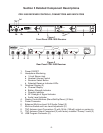
Audio Output
1. The CDR-1000 is equipped with a balanced XLR
output for each receiver that can be switched
between a fixed microphone level (-10dBV) and an
adjustable line level (8mV – 0.775V RMS).
2. For microphone level operation place the Mic/Line
switch in the Mic position. The level adjustment will
have no effect on the output in the Mic setting.
3. For adjustable balanced line level operation place
the Mic/Line switch in the Line position. The level
adjustment will now affect the output.
Antenna Connections
1. The Antenna input connection includes a 15Vdc
source to power the UAA-500 UHF antenna
amplifier for long coax runs and covering large
performance areas.
NOTE: The two flexible ½ wave antennas included
with the CDR-1000 can be remote mounted. For an
additional 5dB gain use the LPA500B log periodic
directional antenna.
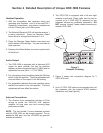
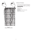
2. The CDR-1000 is equipped with a left and right
antenna output jack. These jacks can be used to
connect up to 3 CDR-1000 (6 receivers) to two
antennas without any additional equipment. DO
NOT remove “dummy” loads unless connecting to
another CDR-1000.
3. Figure 3 shows the connection diagram for 3
CDR-1000 units.
4. Up to 12 CDR-1000 units can be operated with just
two antennas with the optional APD4 antenna
distribution unit (see Figure 4).
CDR-1000
DUAL RECEIVER
PROGRAM 2
AUDIO 2
LINE MIC
LINE
LEVEL
PROGRAM 1
MADE IN U.S.A.
OUT
IN
ANTENNA
AUDIO 1
LINE MIC
LINE
LEVEL
POWER
90-260 VAC 50-60 Hz
12 Vdc
150 mA
Out
PATENTNO. 6,256,484
OUT
IN
ANTENNA
12 Vdc
150 mA
Out
CDR-1000
DUAL RECEIVER
PROGRAM 2
AUDIO 2
LINE MIC
LINE
LEVEL
PROGRAM 1
MADE IN U.S.A.
OUT
IN
ANTENNA
AUDIO 1
LINE MIC
LINE
LEVEL
POWER
90-260 VAC 50-60 Hz
12 Vdc
150 mA
Out
PATENTNO. 6,256,484
OUT
IN
ANTENNA
12 Vdc
150 mA
Out
CDR-1000
DUAL RECEIVER
PROGRAM 2
AUDIO 2
LINE MIC
LINE
LEVEL
PROGRAM 1
MADE IN U.S.A.
OUT
IN
ANTENNA
AUDIO 1
LINE MIC
LINE
LEVEL
POWER
90-260 VAC 50-60 Hz
12 Vdc
150 mA
Out
PATENTNO. 6,256,484
OUT
IN
ANTENNA
12 Vdc
150 mA
Out
THIS END TOWARDTRANSMITTER
UHF
LPA500
R
LOG PERIODIC ANTENNA
THIS END TOWARDTRANSMITTER
UHF
LPA500
R
LOG PERIODIC ANTENNA
Figure 3
Antenna Chaining
-3-