


High Equalizer Control
(HIGH)
The high EQ control alters the
high frequency response of the
input channel, providing ±13dB
at 10kHz, and ±15dB at 20kHz of
continuously variable active
shelving equalization. The "0"
detented position provides flat
audio response.
Low Equalizer Control
(LOW)
The low EQ control provides
±13dB at 100Hz and ±15dB at
50Hz of continuously variable
active shelving equalization.
The "0" detented position pro-
vides flat audio response.
Power Amp Compression
Indicator
(COMP)
The Comp LED lights when the
internal compressor is activated.
The compressor is provided to
protect speaker systems by com-
pressing the input signal level of
the power amplifier when clip-
ping occurs in the output stage.
Frequent flashing of the LED is
not reason for alarm. However, a
constant or steady light indicates
that the MX-104 is being over-
driven and that the internal
power amplifier is possibly
"under powered" for that applica-
tion. The output level of the MX-
104 should be decreased until the
LED only flashes intermittently.
Power Indicator LED
(POWER)
The indicator LED lights when
the power switch is "on".
Input Level Control
(LEVEL)
The level control provides con-
tinuously variable adjustment
of the channel output to the
program mixing buss, thus
determining the level of that
channel in the main sound
system mix. Since the reverb
signal is "post" this control, an
increase in the level of the
channel's output will also result
in a corresponding increase in
the reverb effect of that channel.
The nominal level of the input
level control is at the "10" posi-
tion.
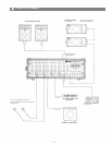
High Impedance Connectors
(HIGH Z)
These connectors are unbal-
anced, standard 1/4" phone jacks
with an input impedance of 27k
ohms, and an input level of
-35dB. When a plug is inserted
into the high -Z input, the cor-
responding XLR connector is
automatically switched out of the
input circuitry.
Low Impedance Connectors
(LOW
Z)
The XLR connectors are low im-
pedance, electronically balanced
inputs with an input impedance
of 1k ohms.
Reverb to Program Contro1
(REV
TO
PGM)
This control adjusts the amount
of reverb signal that is returned
to the program buss and thus the
level of reverb contained in the
main sound system.
Program Master Control
(PGM)
The PGM control adjusts the
overall combined signal level of
the four independent channel
level controls, and thus the level
of the main sound system.
Aux Input Jacks
(AUX
IN)
The phone jack and RCA pin
jacks are wired in parallel, with
an input level of -20dB. When a
plug is inserted into the phone
jack, the RCA pin jacks are
automatically switched out of
the AUX circuitry.
Foldback Output Jack
(FB
OUT)
This jack is for connection to
external power amplifiers and/
or equalizers for the on-stage
monitoring system. Nominal
output level is +4dB with an
impedance of 600 ohms. If the
internal power amp and equal-
izer are to be used for the on-
stage monitor system, the FB
output should be connected to
the GEQ input jack.
Program Output Jack
(PGM OUT)
The PGM Out jack is provided
for connection to external equal-
izers and/or power amps, deriv-
ing its signal prior to the internal
GEQ and power amp. Nominal
output level is +4dB with an
impedance of 600 ohms.
Graphic Equalizer Input Jack -
(GEQ
IN)
The GEQ input jack allows the
graphic equalizer to be used in-
dependently of the MX-104 with
other external equipment, or the
internal power amplifier and the
graphic equalizer with external
equipment. When a plug is
inserted, the main mix from
the program buss is disconnected
from the graphic equalizer and
the power amplifier. The nomi-
nal input level is +4dB with an
input impedance of 50k ohms.
Graphic Equalizer Output Jack
(GEQ OUT)
This jack allows the MX-104
and the internal graphic equal-
izer to be used with an external
power amplifier, or in conjunc-
tion with the GEQ in jack, to be
used independently of all other
MX-104 circuitry. Nominal
output level is +4dB with an
impedance of 600 ohms.
Power Amp Protection
Indicator (PROTECT)
The indicator LED lights if the
power amplifier output is short-
ed, if the temperature of the unit
rises above acceptable levels, or
if DC is drifted to the speaker
outputs. If the LED should light,
speaker wiring and ambient
temperature of the MX-104
should be checked. If the LED
remains lighted, the unit should
be referred to qualified service
personnel for repair.
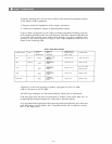
Note:
The MX-104 protection circuitry
will (1) detect 'faulty conditions'
within the power amplifier, (2)
give a visual indication, and (3)
automatically shut down until
the fault condition is alleviated.
This special circuitry ensures
maximum reliability and vir-
tually eliminates equipment
damage due to unsafe or fault
conditions. Please refer to fault
protection table on page 4 for
full explanation of this im-
portant feature.
Power Amplifier Input Jack
(PWR
IN)
The PWR Amp input jack allows
the internal power amplifier to
be used with external equip-
ment. When a plug is inserted,
the power amp is automatically
disconnected from the MX-104
mixer section. The nominal in-
put level is +4dB with an input
impedance of 10k ohms.
— 3 —
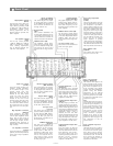
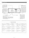
Front Panel
Reverb to Foldback
Control (REV TO FB)
This control adjusts the amount
of reverb signal that is returned
to the foldback buss and thus the
level of reverb contained in the
on-stage monitor mix.
Reverb/Control
(REV)
This control determines the
level of signal assigned to the re-
verb mixing buss. Rotating the
control clockwise increases the
amount of reverb in that channel.
Foldback Control (FB)
The Foldback control deter-
mines the level of signal assign-
ed to the foldback mixing buss,
thus setting the level of that
channel in the on-stage monitor
mix.
Graphic Equalizer
(EQUALIZATION)
The graphic equalizer is 5 inde-
pendent active bands (filters),
providing 12dB of boost or cut at
each center frequency. The "0"
detented position provides flat
audio response.
Foldback Master Control (FB)
The FB master control adjusts
the overall combined signal level
of the four independent channel
foldback sends, and thus the
level of the entire on-stage moni-
tor
mix.
Aux Level Control (AUX)
This control sets the overall level
of the Aux input signal.